Welcome to my digital portfolio! I am a second year student pursuing a BASc in Manufacturing Engineering at the University of British Columbia, expecting to graduate in 2030.
This is an evolving space to showcase projects and experience from both my personal and academic work as I continually create and do new things.
Thank you for visiting! Feel free to reach out.
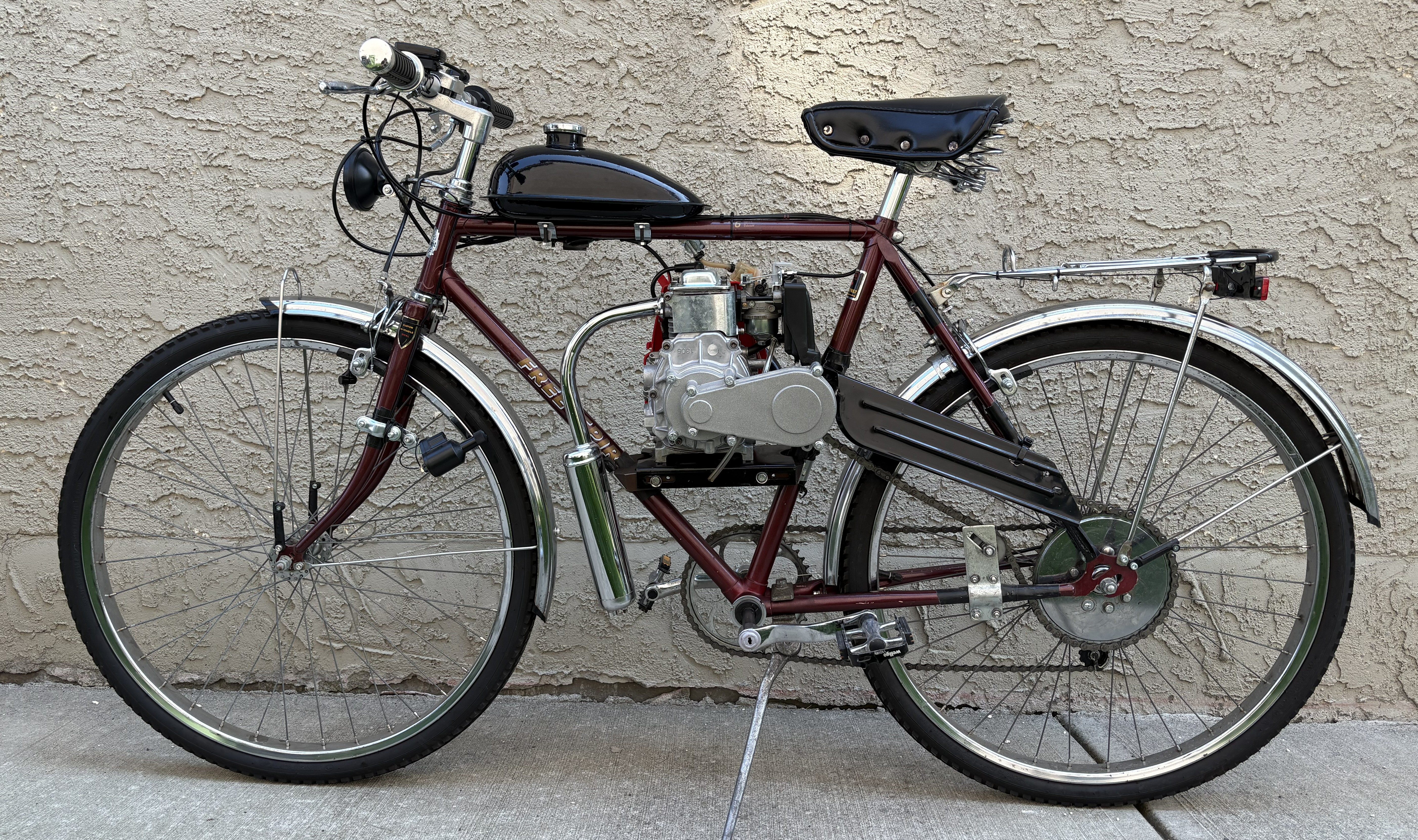
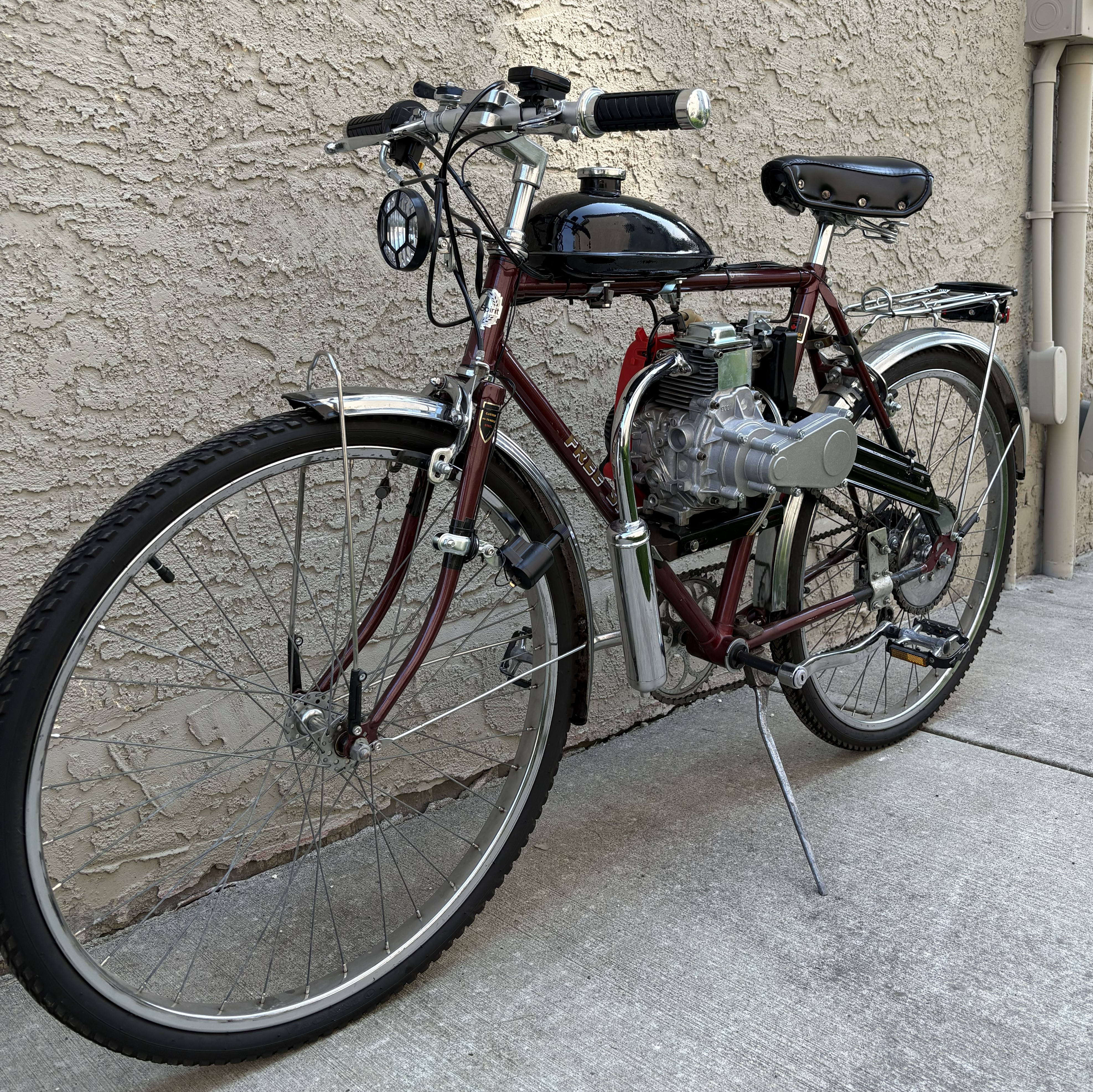
This project began with the goal of creating a small, low-cost vehicle compliant with Alberta moped laws, that manifested itself into a 50cc cafe-racer styled motorized bike, inspired by early motorcycles.
Using a modified Honda GXH50, the completed bike was road-tested to 80 km/h.
What began as a personal project quickly became an opportunity to practice mechanical design and fabrication, to study engine mechanics, and problem-solve to create a cohesive working vehicle.
The platform of the build is a 1970s Free Spirit steel bicycle, which I restored prior to its use in this project. Restoring the original frame provided an opportunity to inspect and adapt the components to ensure they could handle increased speeds and additional loads with the motorized conversion.
After acid-bathing the components to remove rust and grease accumulation, cleaning and re-greasing the bearings, and retuning the brakes and gears, the bike was fit for the installation of the engine.
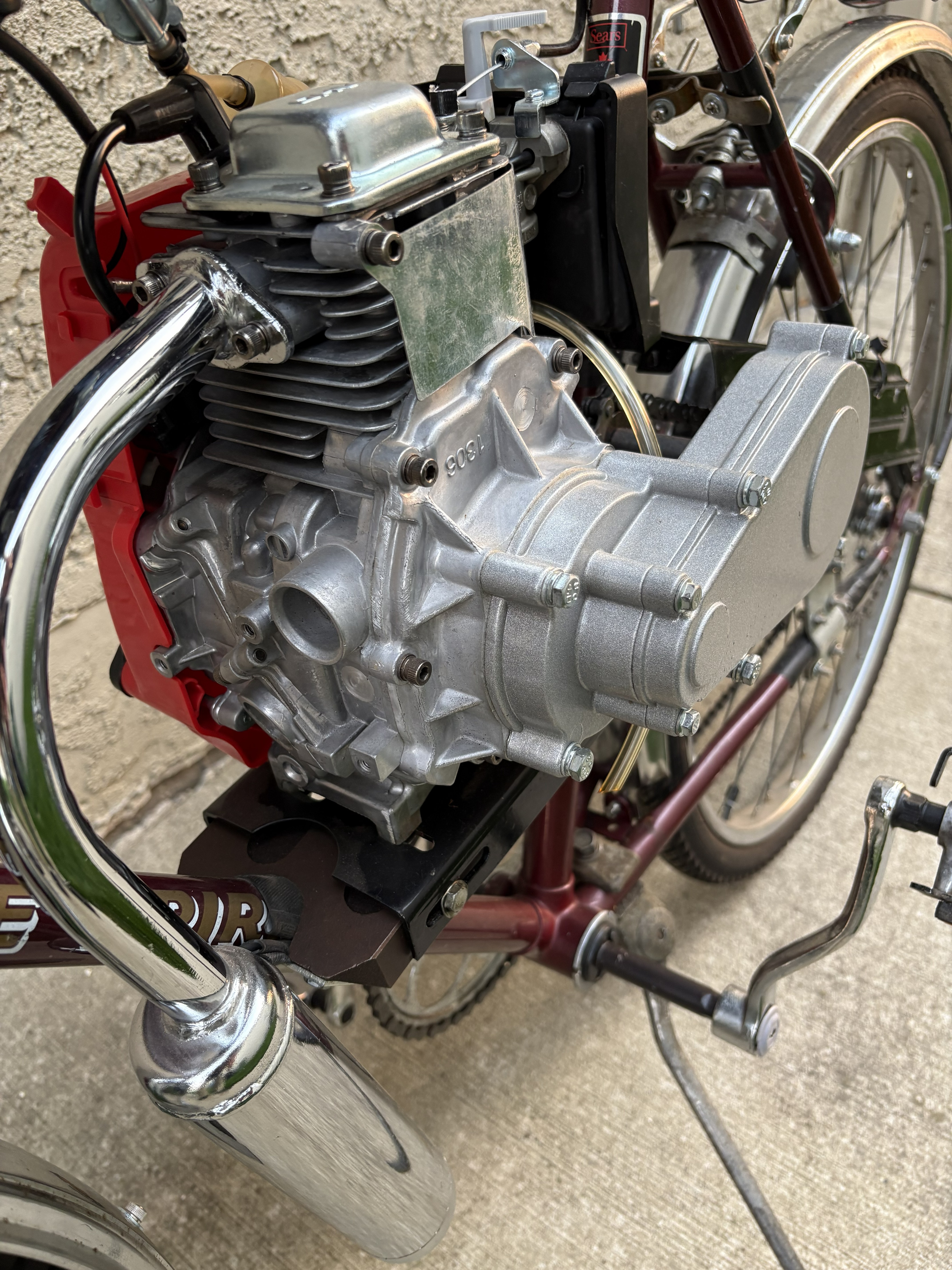
To integrate the engine components into the constraints of an existing frame, iterative modifications and adjustments were required throughout the process of the build. The engine itself was mounted inside the frame using cast-iron joints and a sheetmetal base.
The addition of the engine came with the installation of a rag-jointed rear sprocket, centrifugal clutch, throttle cable, kill-switch, fuel tank, and lights.
View of the engine
To optimize performance, various adjustments were made. The carburetor was tuned to run a lean fuel-air mix. While reducing low-rpm power, this configuration increased performance at high-rpm in testing. The air intake and the exhaust were modified to allow greater airflow, lessening resistance on the engine, and the overhead valve's clearances were adjusted to improve high-rpm airflow. To compensate for the loss of low-rpm power, the centrifugal clutch springs were stretched to improve low-end engagement.
Costing under $600 and using parts available online and locally, the build balances performance, accessibility, and serviceability.
Parts were selected with replicability in manufacturing and future replacement in mind, while retaining simplicity.
Although the build relies on simple fabricated hardware and minor part modifications, this allows for replication by using low-cost, commercially available parts.
The completed build provided a hands-on experience with mechanical design and assembly where design decisions had immediate, observable effects on the performance of the vehicle.
It was also an exercise in assembling interworking systems to create a coherent and working product.
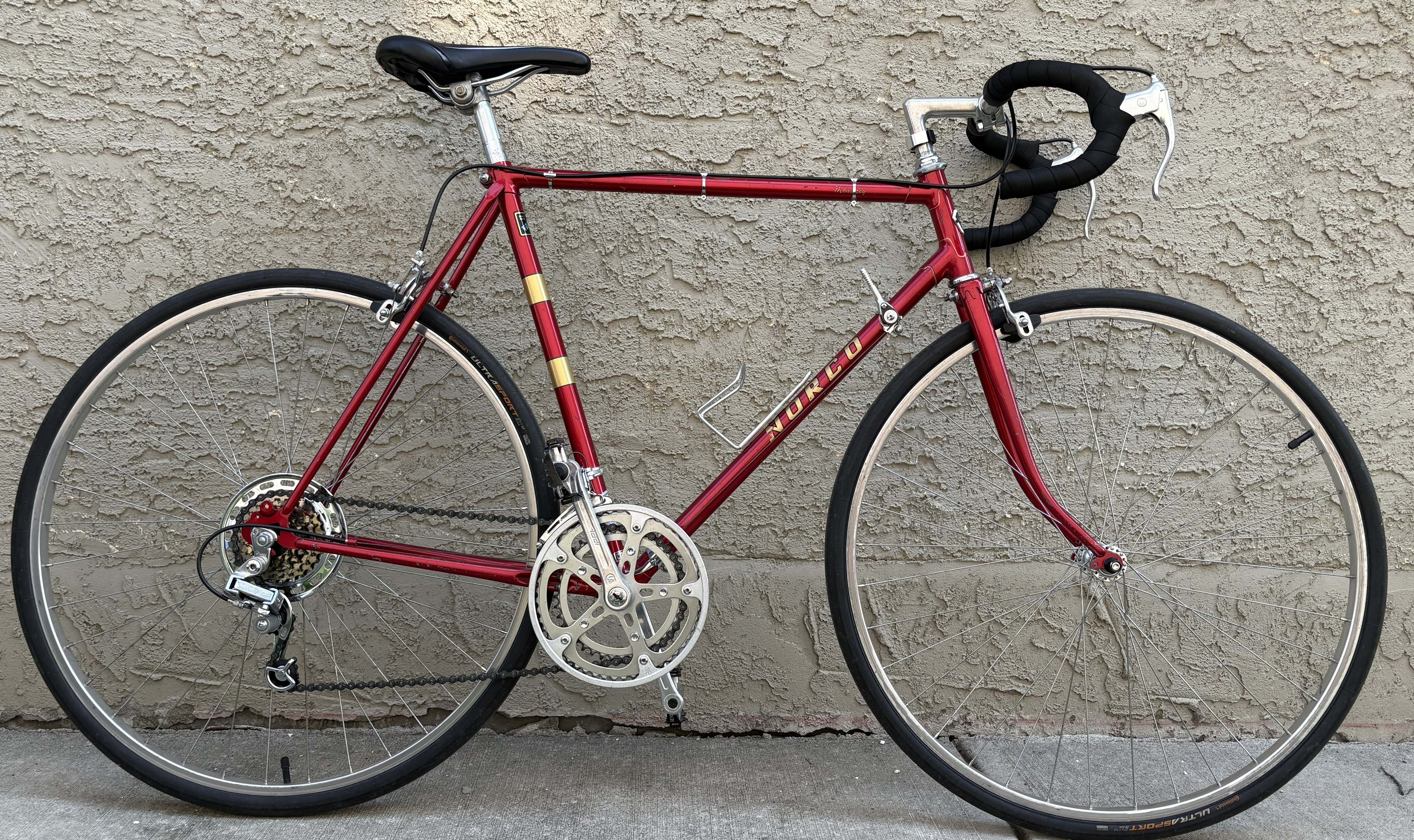
Considered road bike platform
Considered mountain bike platform
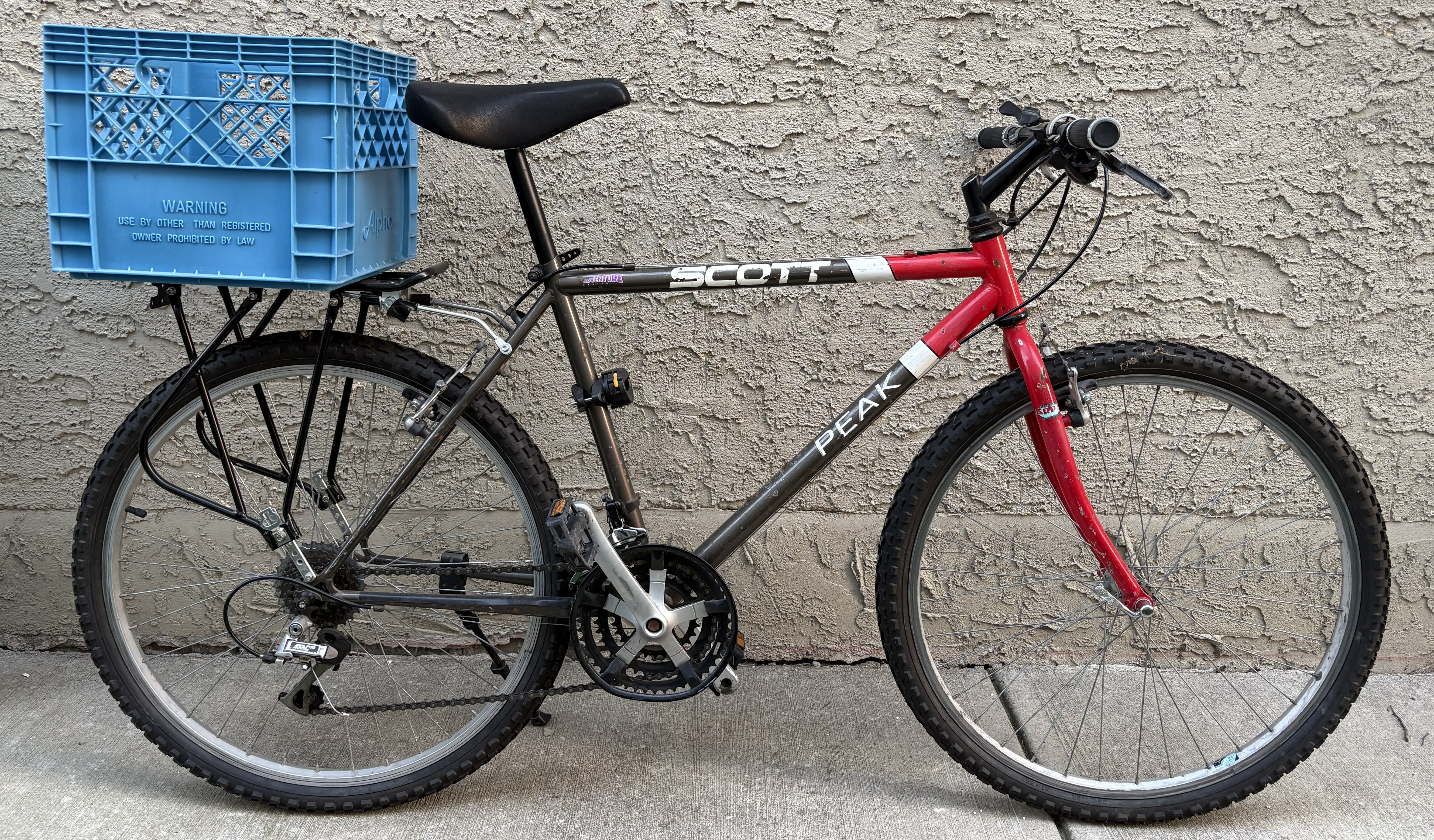
Two other restored vintage bicycles were considered as potential platforms for the build; one road bike, and one mountain bike. Restored in a similar fashion, they were rebuilt and tuned, but were deemed less capable than the Free Spirit frame to handle an engine conversion due to geometry and road capabilities. The Free Spirit frame had the additional benefit of being constructed from steel; able to absorb vibrations and slightly flex under load further made it a well-suited option.
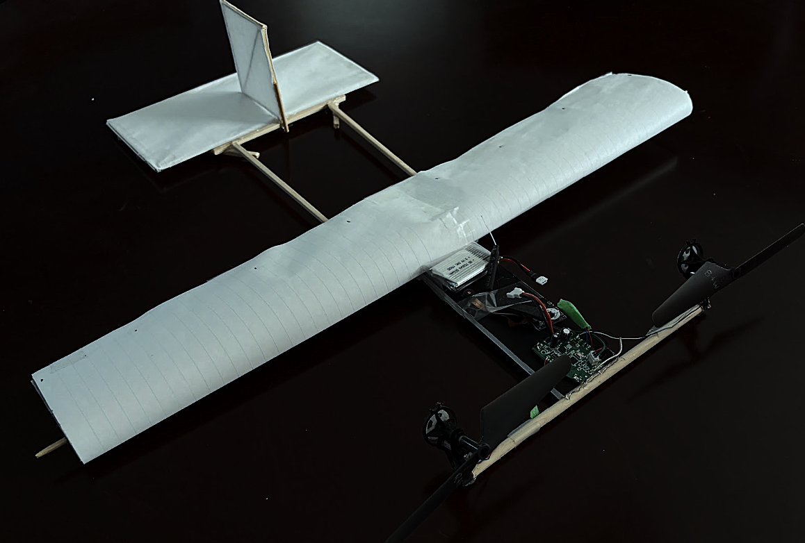
Constructed from foam board, balsa wood, and paper, this ultralight radio-controlled airplane has a gross weight of under 180 grams.
This plane utilises components sourced from a recycled drone. The constraints of the low-torque motors are reflected in the lightweight design through material choice and minimalist construction.
Additionally, a dual-propeller design was conceptualised to retain maneuverability without additional weight and mechanical complexity of conventional ailerons and a rudder.
Differential thrust between the two motors eliminated the need for these two systems entirely.
The final design of this airplane was reached through a process of iterative prototyping. Since this project was heavily constrained by the low power of the motors, 3 prototypes were studied before the final design, to perfect the weight balance and aerodynamics to acheive stable flight.
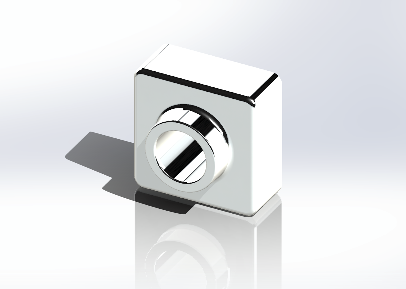
This small CAD project was completed as a part of the first-year curriculum in UBC Engineering, and was my first introduction to SolidWorks.
Although simple in nature, this project introduced me to sketching parts and fundamental SolidWorks features, including extrusions and cuts. It provided an early foundation for developing my CAD and 3D modeling skills.
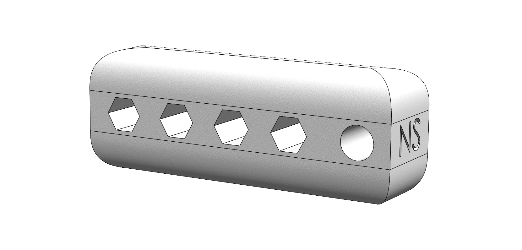
My next CAD project was a simple keychain. Featuring the use of a linear pattern and the embossing of letters, I further developed the scope of my capabilities in CAD.
This was my first experience using SolidWorks to actually create a product for 3D printing.
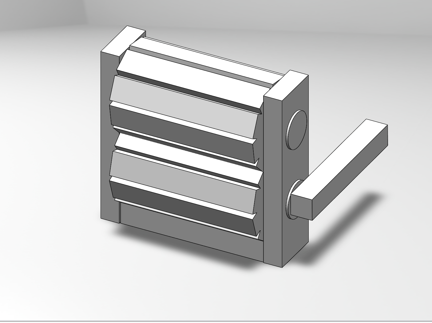
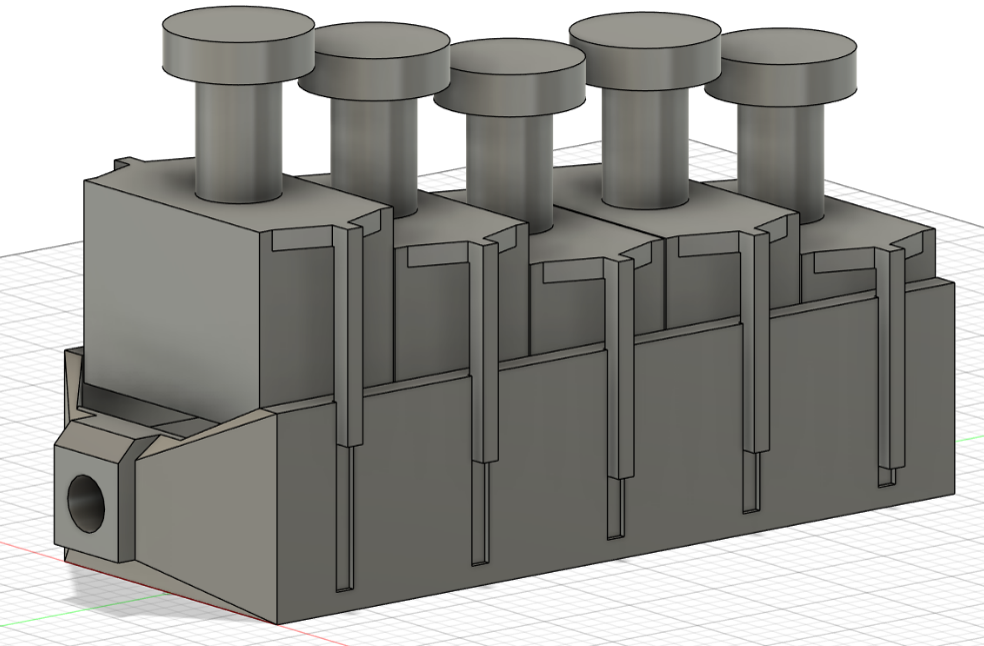
This project is a prototype of a tube squeezing device, as part of a greater project in the first-year curriculum to design a manufacturable adaptive device for those with limited mobility.
This was my first experience designing a product with a design-for-manufacturing mindset. I also learned assembly modelling in SolidWorks, combining individually designed components to create the final product.
To further develop my CAD skills, I began taking on more projects to explore and practice more SolidWorks features.
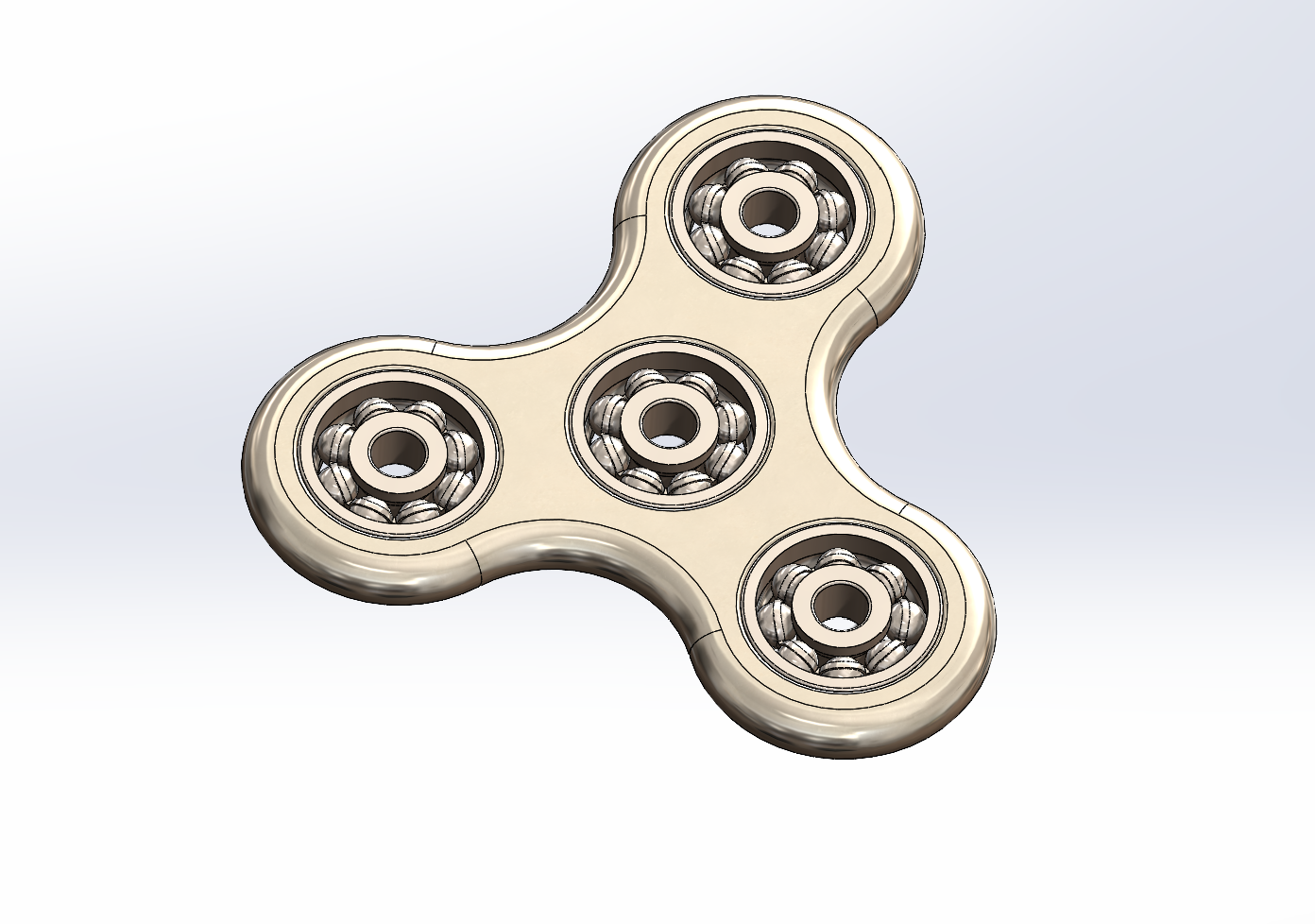
This fidget spinner project introduced me to more advanced SolidWorks features, including circular patterns and the use of standard bearings.
I also learned to use mates to define and observe the motion of the assembly.
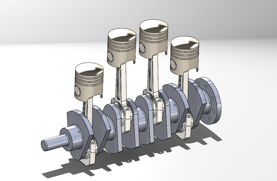
From a set of isometric drawings sourced online, I modelled the individual components, and assembled them into a crankshaft and piston assembly.
This project was significantly more rigorous than my previous work, and further familiarised me with using SolidWorks for more complex assemblies.
With a system of mates and the motion study function within SolidWorks, I was also able to define the motion of the assembly and simulate its real-world motion.
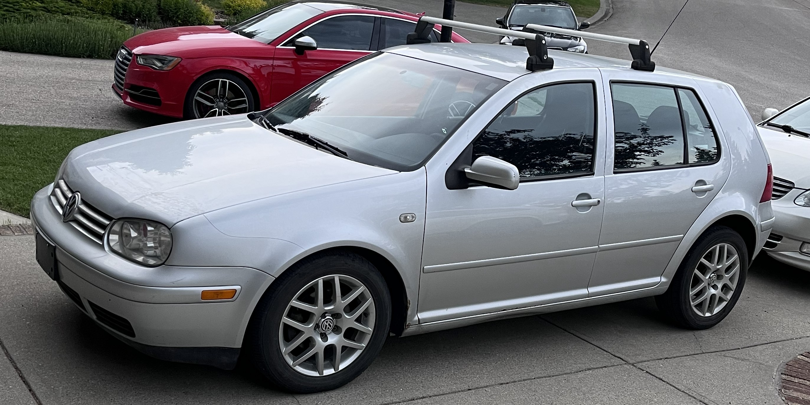
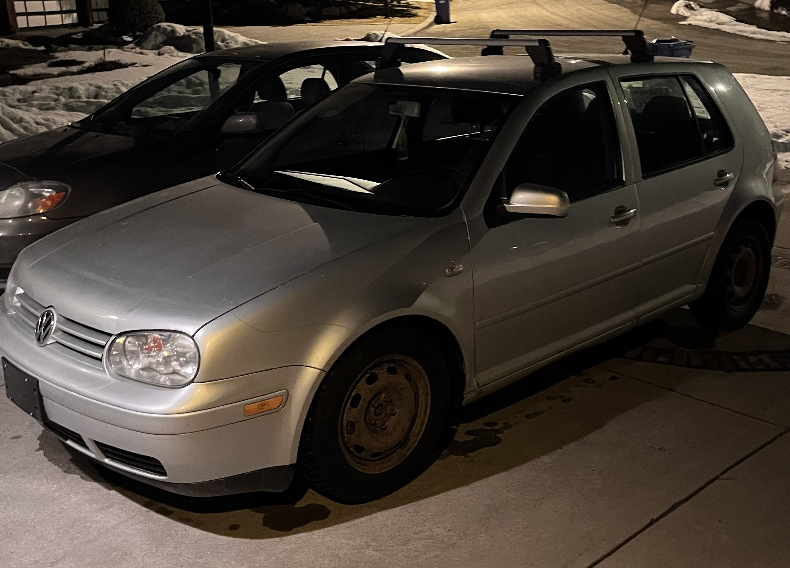
As it stood post restoration
What started as the purchase of a vehicle soon turned into a continuous project of restoration and maintenance. While initially driveable, this Volkswagen Golf was in no sense a perfect vehicle; mechanically and cosmetically it needed attention. In fact, when first purchased, it was taken to a mechanic for an inspection, who then quoted over $4000 for repairs. Refusing to pay nearly the amount I paid for the car itself in repairs, with an inclination to learn, I decided to do the work myself.
As it stood on day one
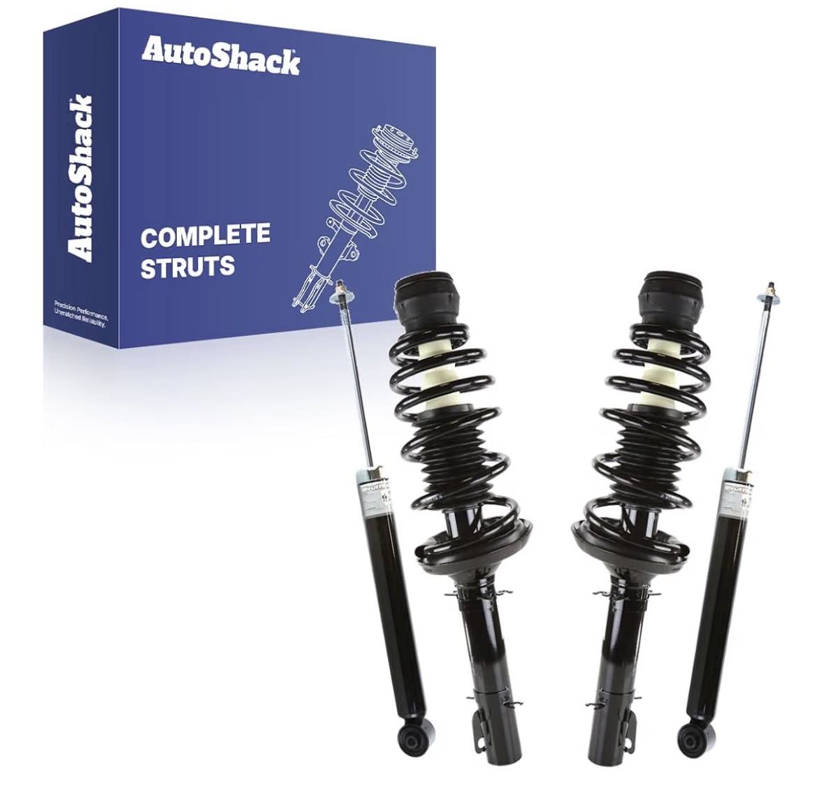
The first work to be done was to return the vehicle to mechanical soundness. This work included full brake replacement, a front suspension rebuild, and rear shock replacement.
Note that at the time, I was not documenting my work with the intention of also making a portfolio. For this reason, many of the images I have of this project only detail
the prior state of the vehicle, as a reference to how components were to be reassembled.
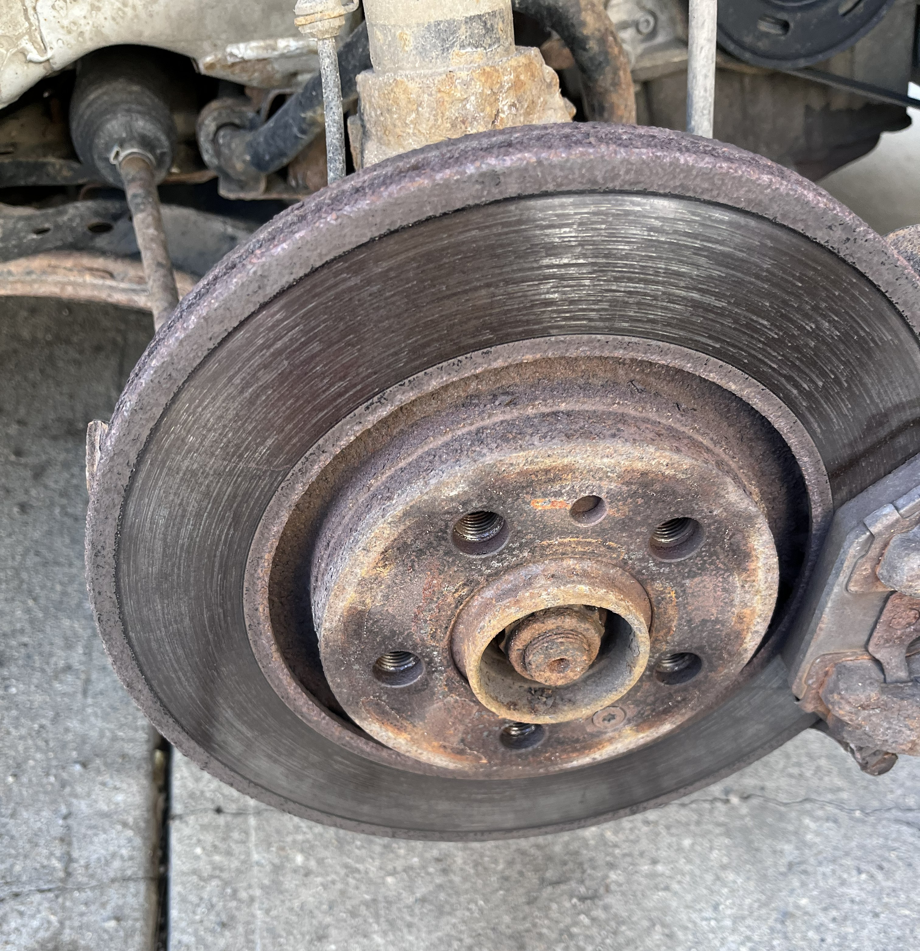
Initial state of the brakes
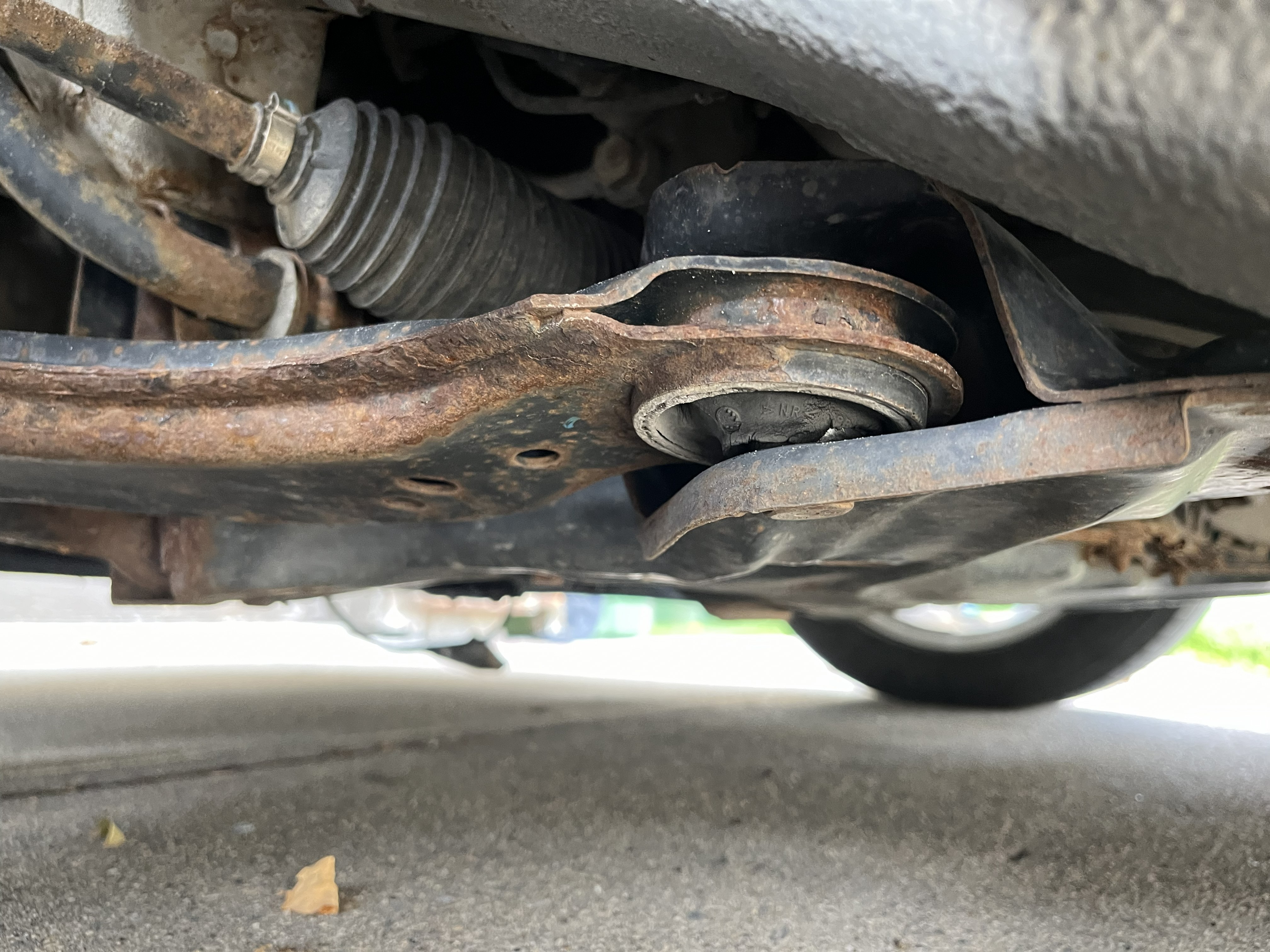
Initial state of the control arms
For their role in safety and handling of the vehicle, and their deteriorated state, I conducted a full replacement of the brakes and suspension assemblies. For the brakes, all rotors and pads were replaced, as well as the rear calipers. The rear shocks were replaced along with the front struts, control arms, and sway bar links. Rather than addressing each issue in isolation, this work was completed at once, navigating issues such as rust and narrow part fitment. The effects on the drive quality were immediate; braking felt solid, but most importantly, improved ability to remain stable in cornering and over rough surfaces came with the suspension rebuild.
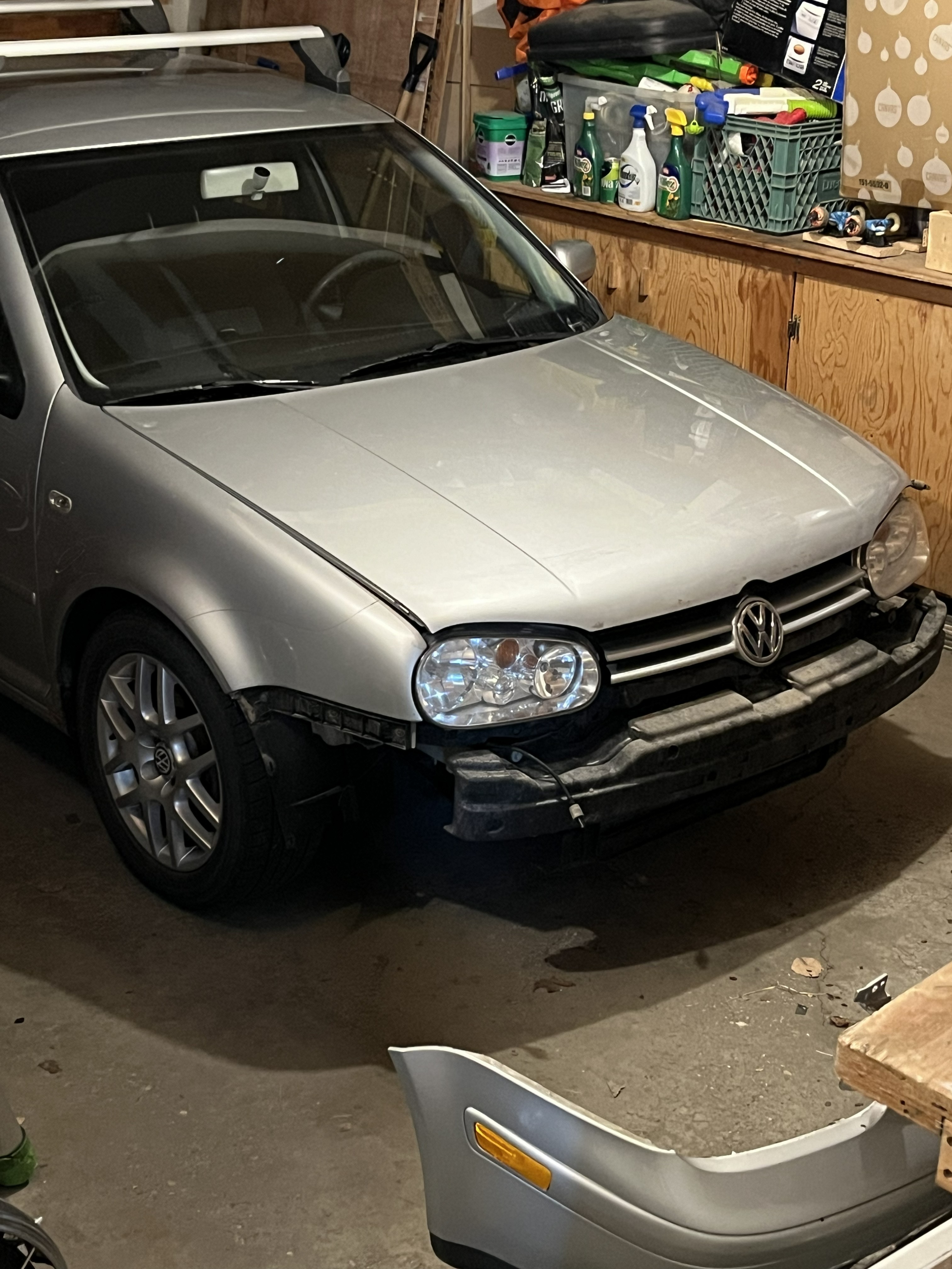
Removing the front bumper
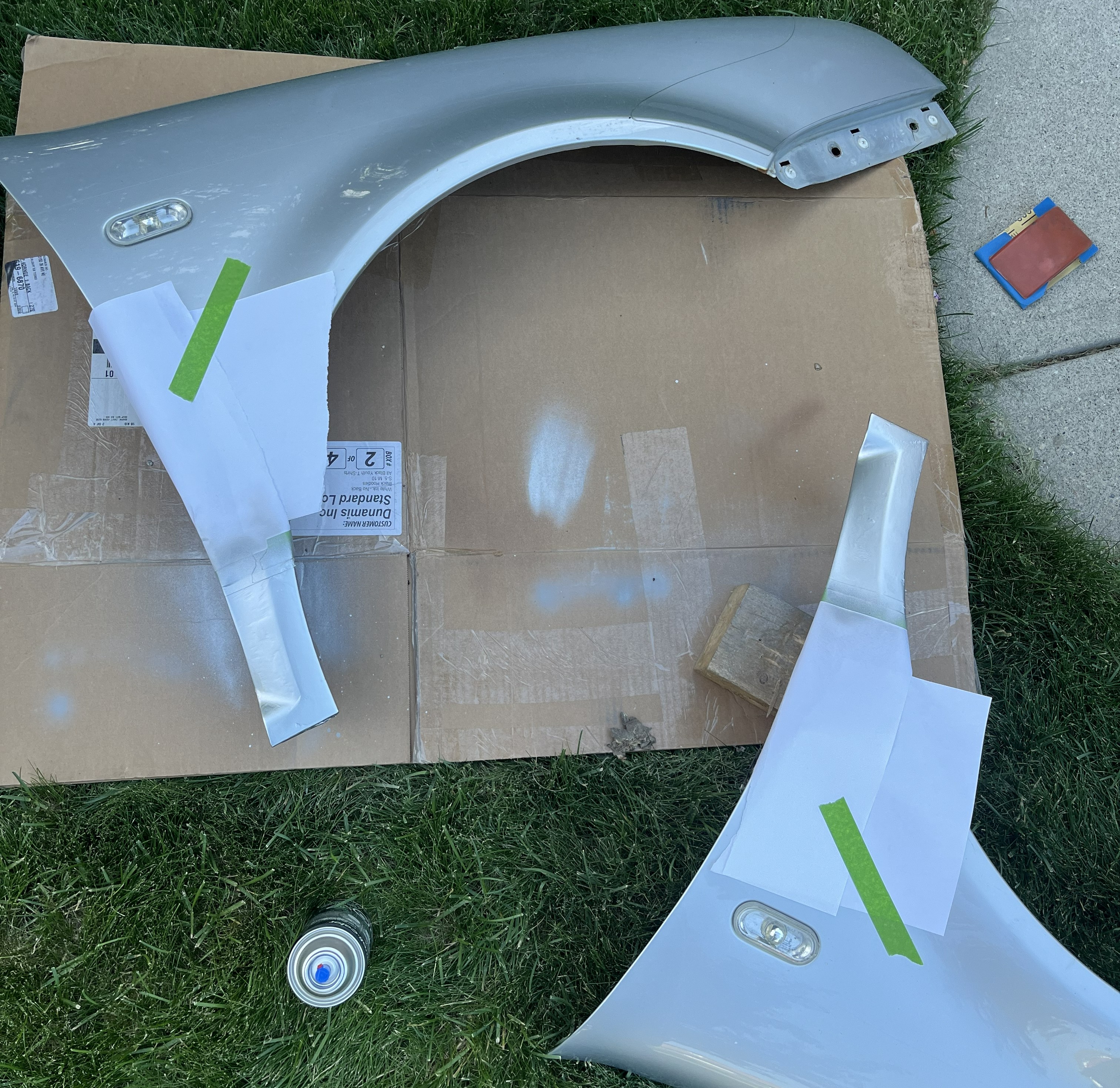
Painting the fenders
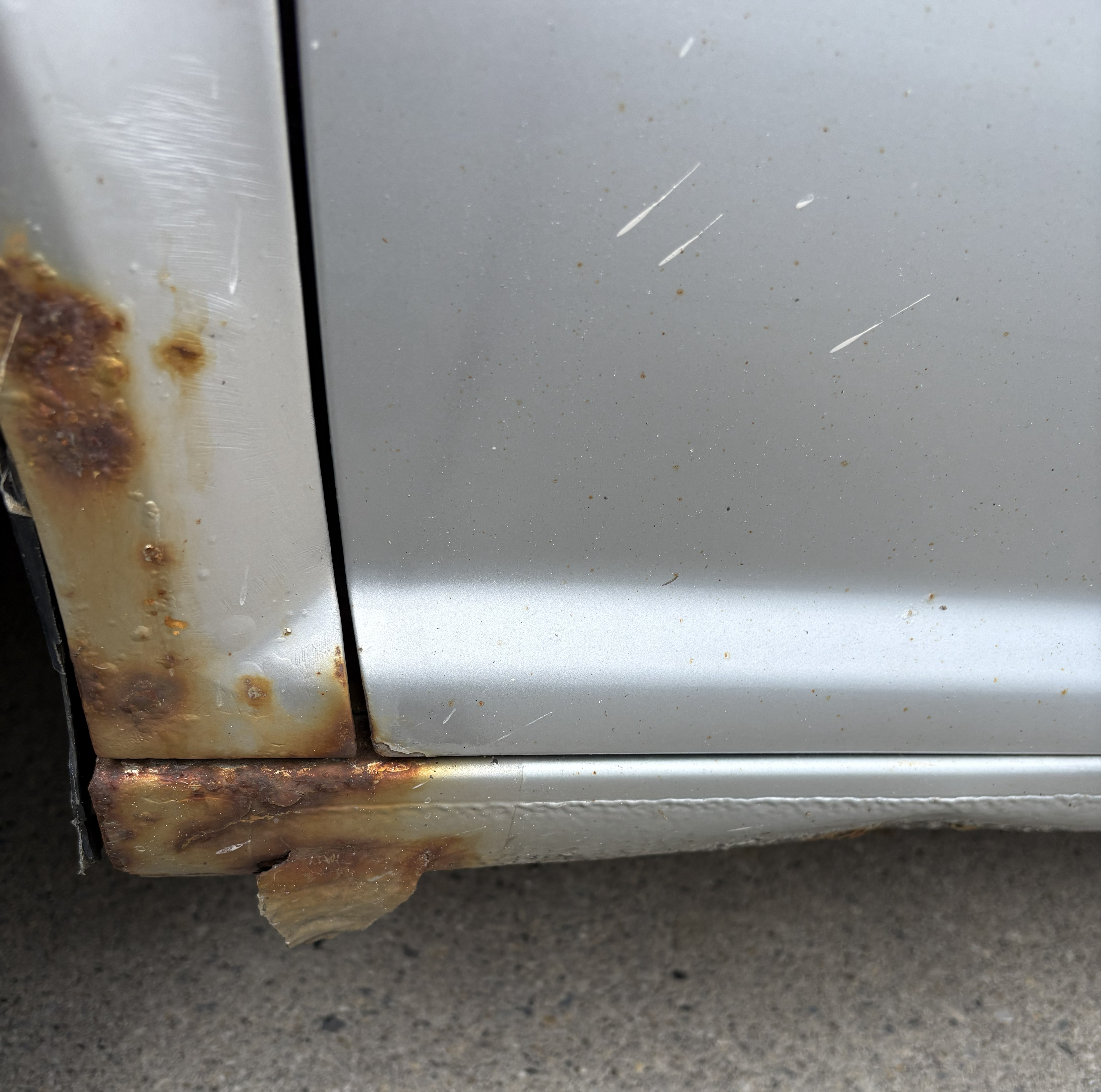
After addressing major mechanical concerns, I began to work on cosmetic restoration. Around the front fenders, rust and corrosion was perpetuating through the paint, not only diminishing the car's visual appeal, but eventually threatening the structural integrity of the body.
Initial state
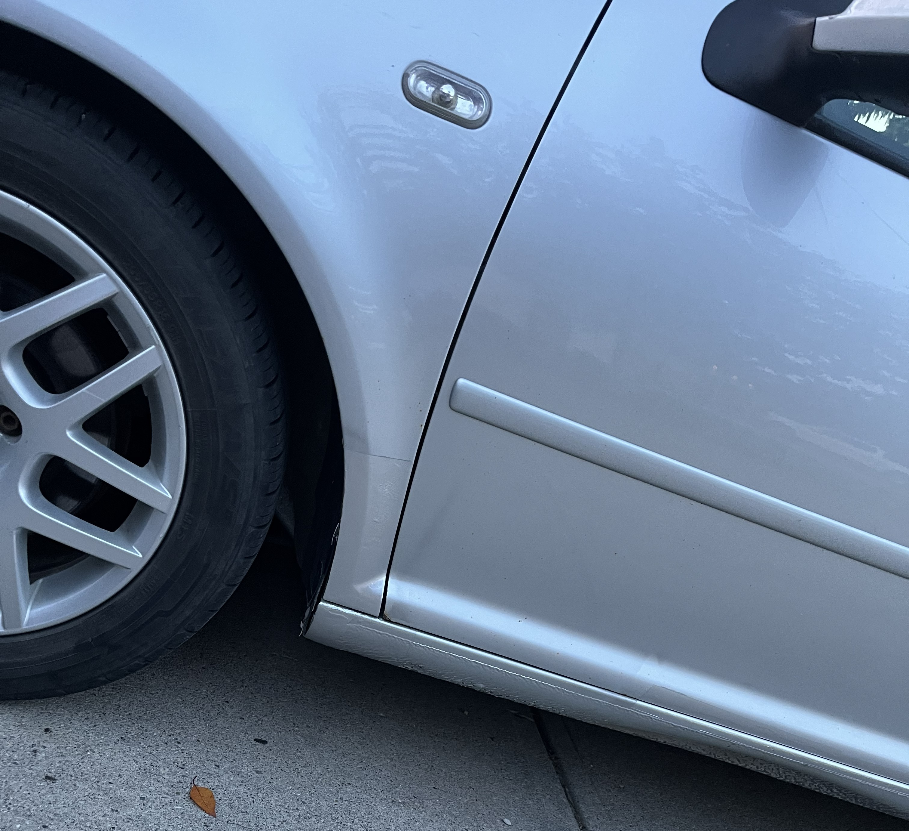
Restored state
The front bumper was removed to give access to the fenders, which were then removed for thorough restoration. The damaged areas were sanded to bare metal to remove existing old paint and rust before body filler was applied to restore the surface and volume of the fenders. The fenders were then primed, painted, and clear coated to restore them to their factory appearance. The same process was carried out on the side skirts, which had also developed rust and corrosion.
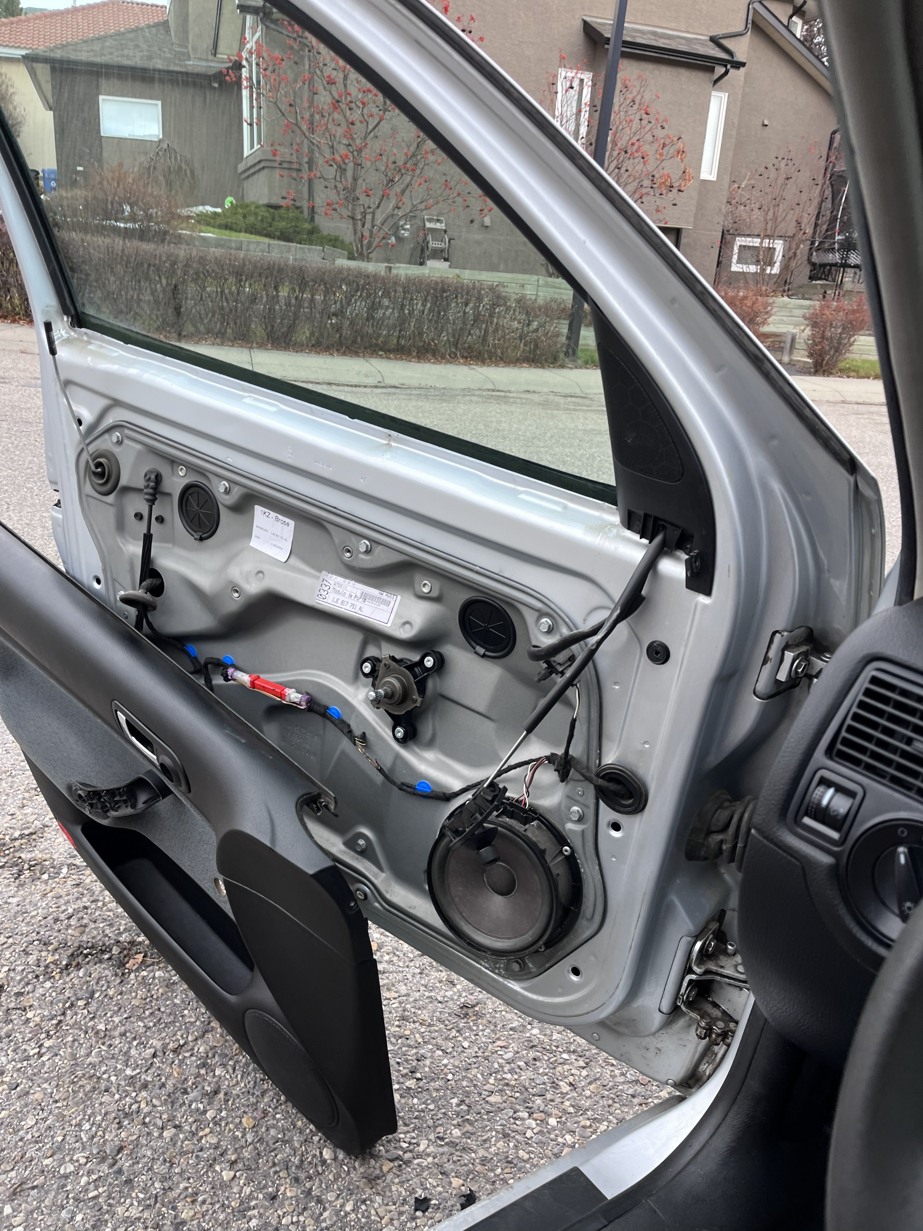
Removing the driver's door panel
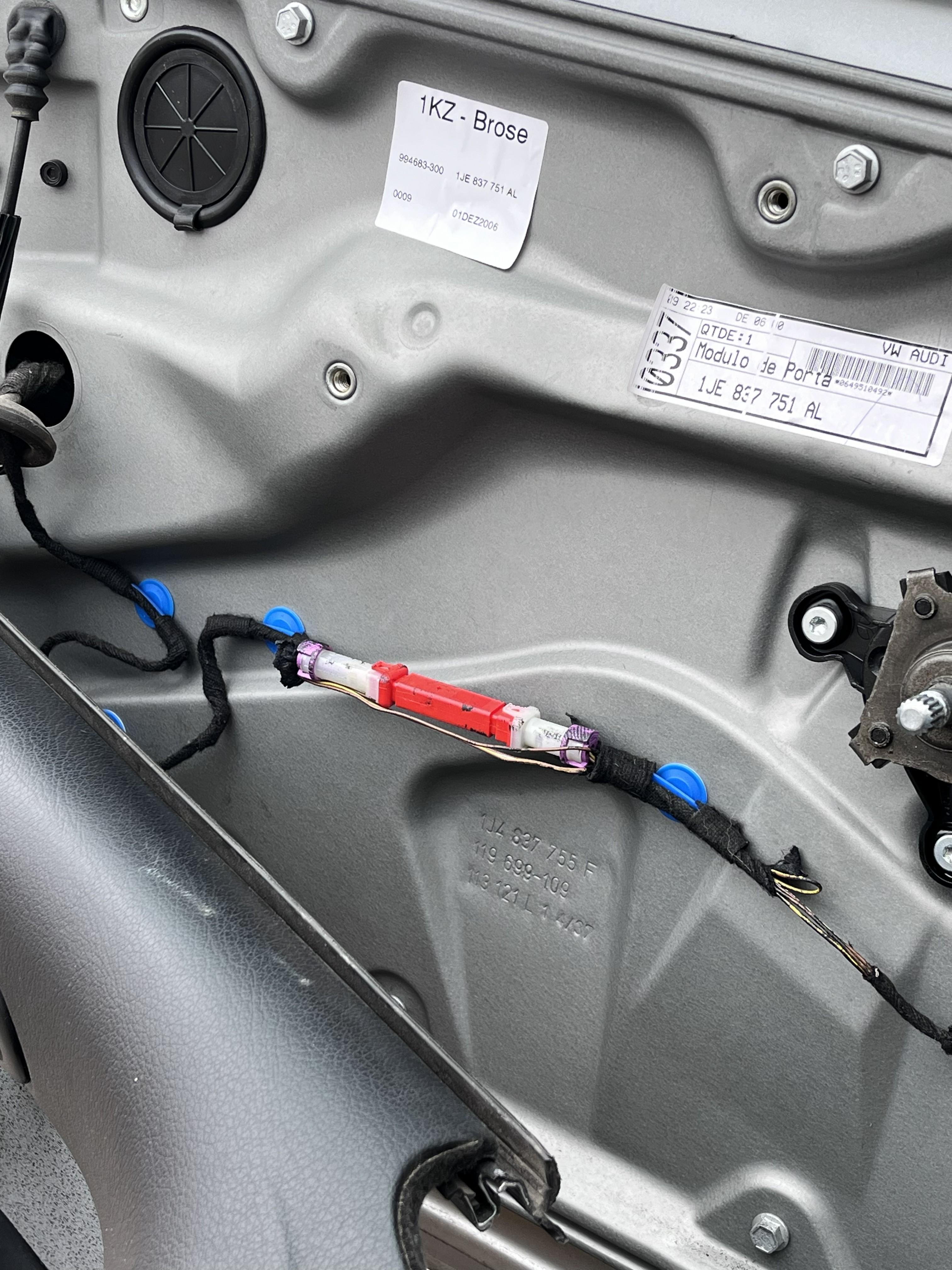
Replacing the door sensor diode
The next problem addressed was the faulty driver's side door-open sensor, which was intermittently failing to register when the door was opened and closed. Removing the door panel provided access to the electronics, and exposed the diode that was responsible for an unreliable electrical current to the door sensor. As such, this component was replaced, restoring the door sensor to working order.
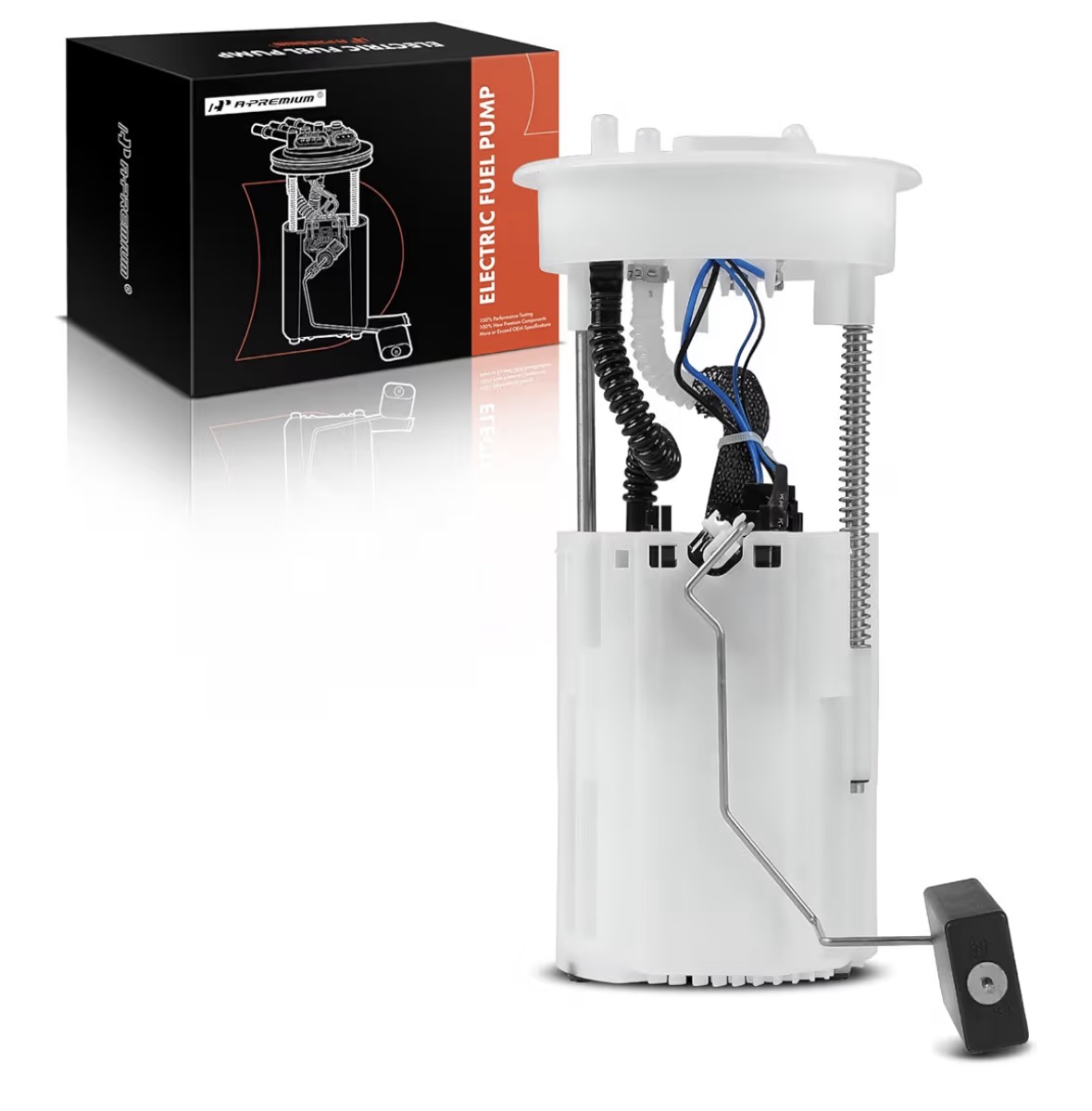
Fuel Pump
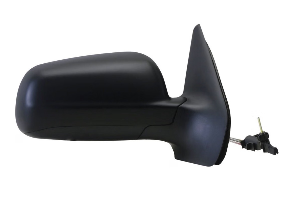
Mirror Replacement
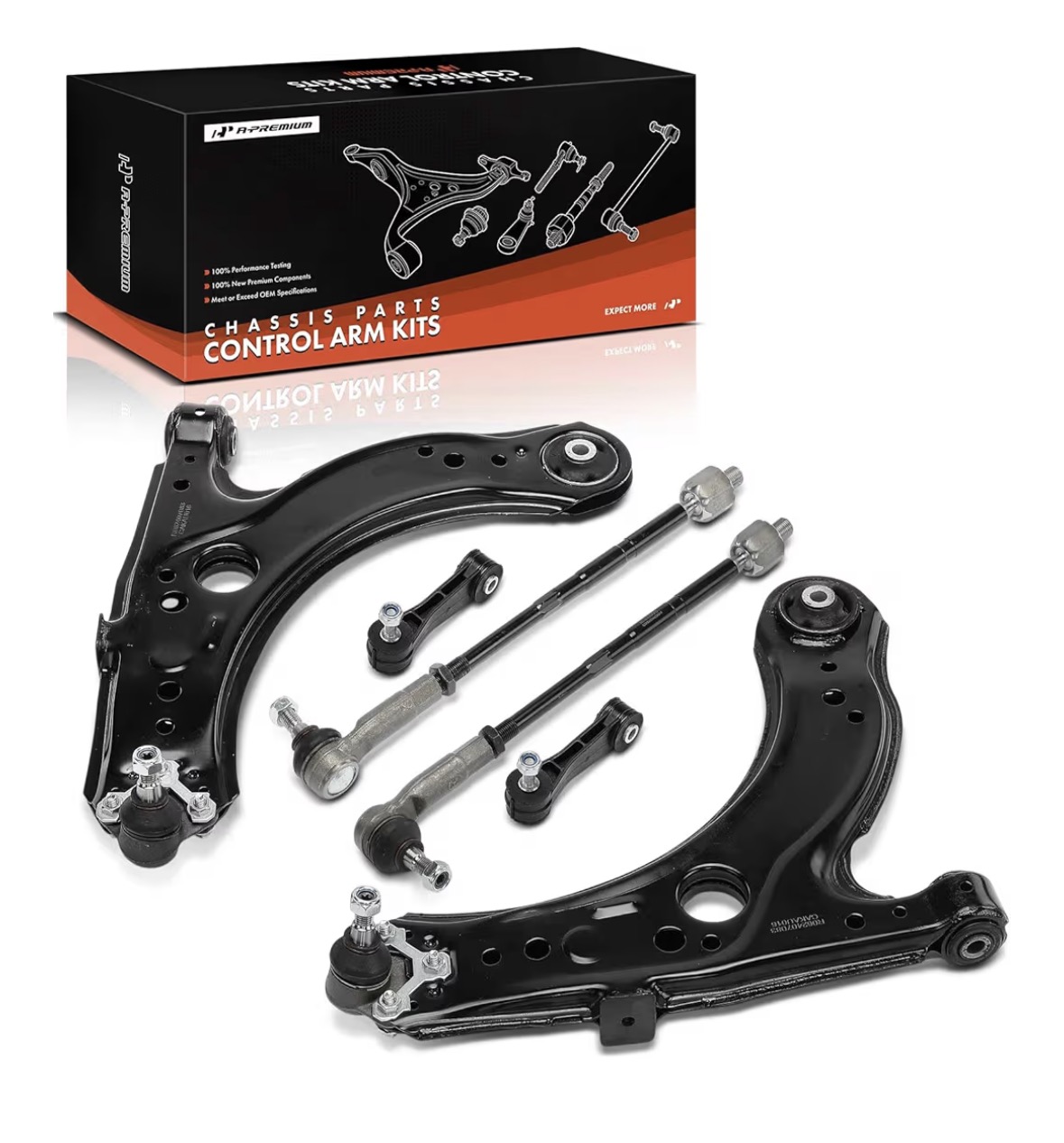
Control Arm Components
Suspension Components
New Components Used on the Vehicle
As some of the work conducted on the vehicle was unfortunately not documented, pictured are some of the new components used on the restoration.
Two replacements were undocumented; a fuel pump replacement to replace the sudden failure of the OEM one, and a left mirror replacement to replace the original which was cracked.
The new control arms and suspension components are also included.
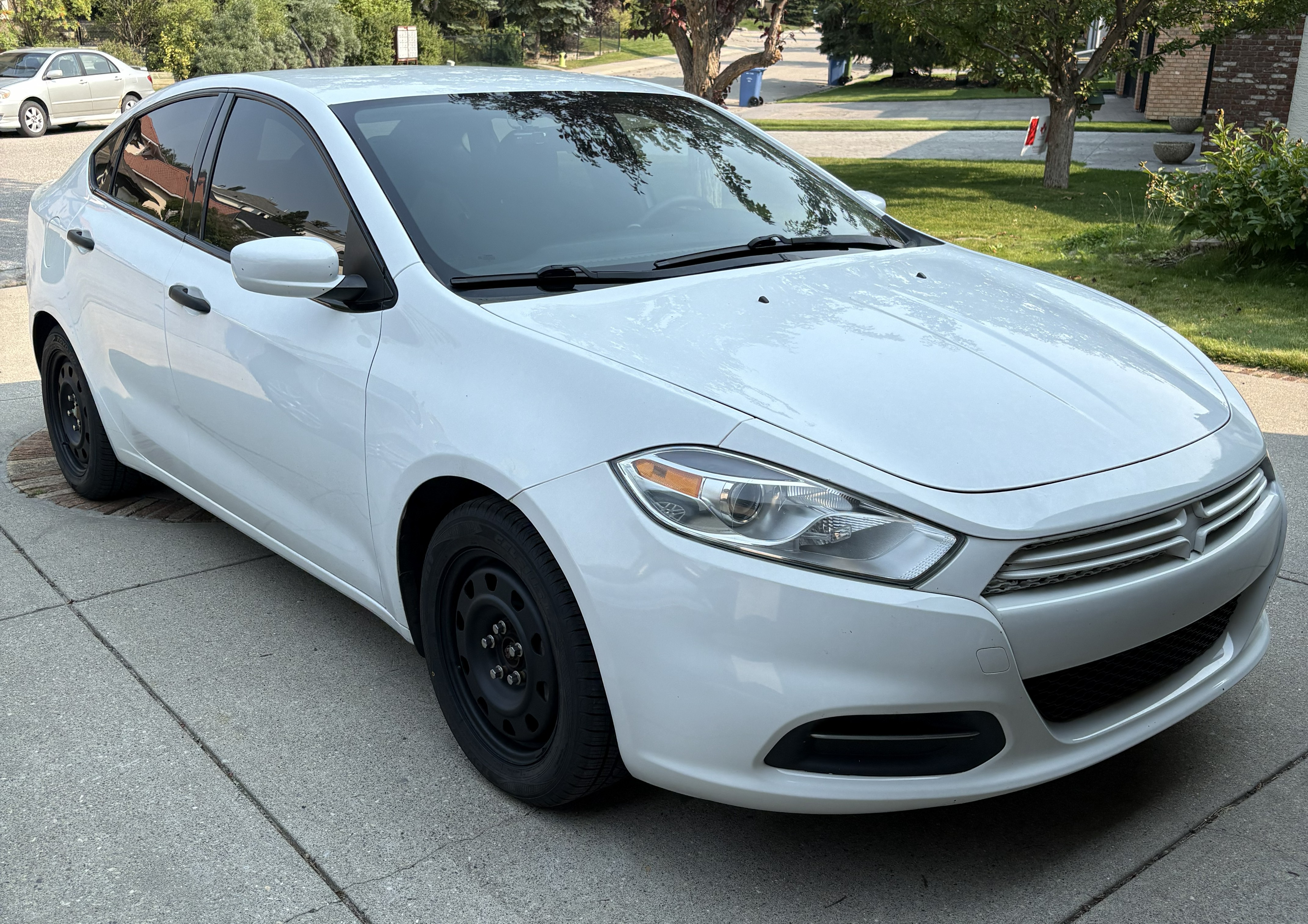
The Dodge Dart as it stands
This Dodge Dart PF is an ongoing project as I navigate maintenance, repairs, and upgrades throughout my ownership.
Since purchasing this vehicle in the summer of 2026, I have already completed some necessary mechanical and cosmetic work.
Aside from continued maintenance, I soon plan to carry out a rear sway bar upgrade and front strut replacement to improve handling.
After purchasing this vehicle in summer 2026, a few immediate areas of concern were identified. These were addressed to retain mechanical fitness and cosmetic appearance.
Old Brakes
New Brakes
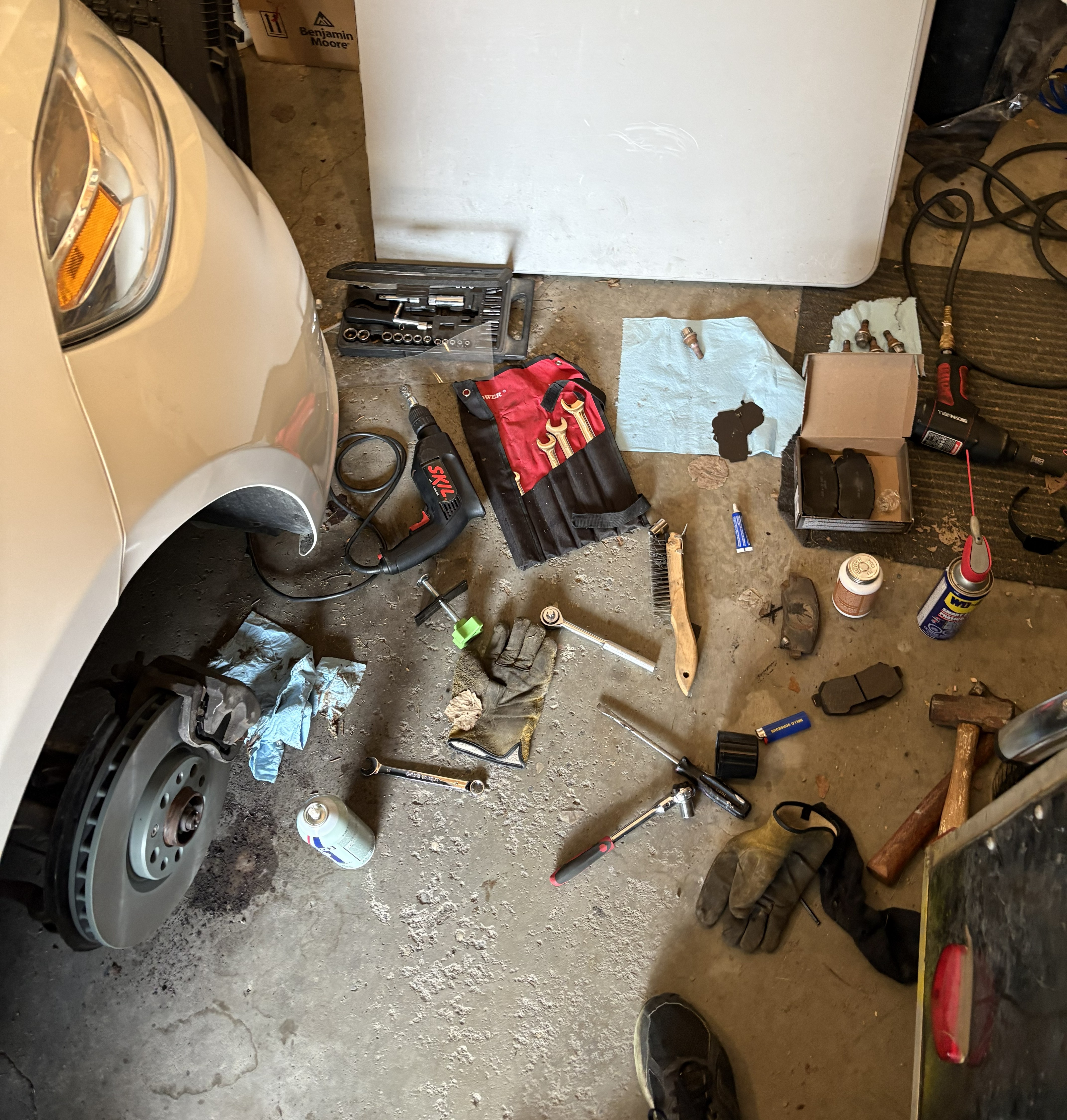
Array of Tools Used
Servicing the Brakes
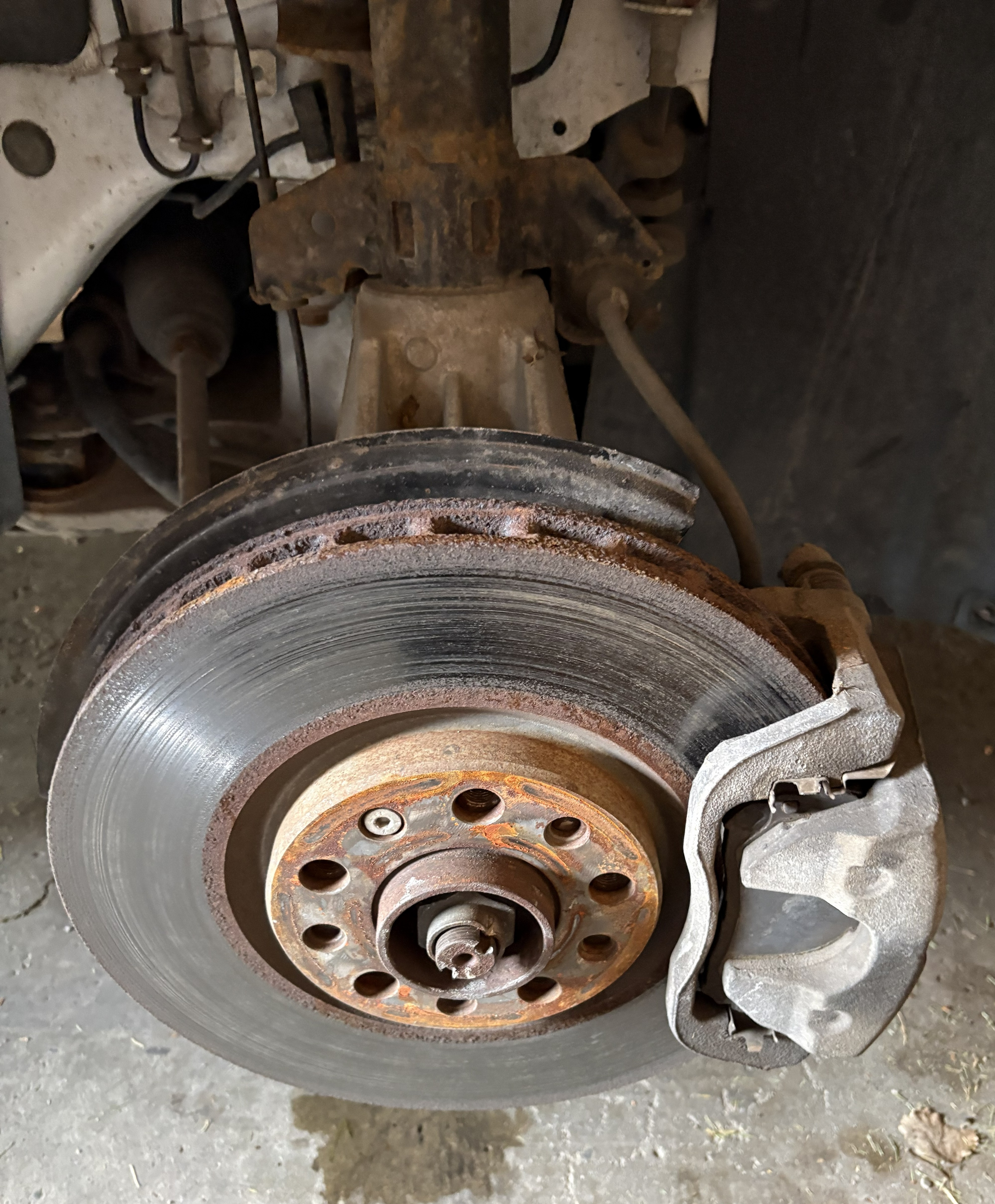
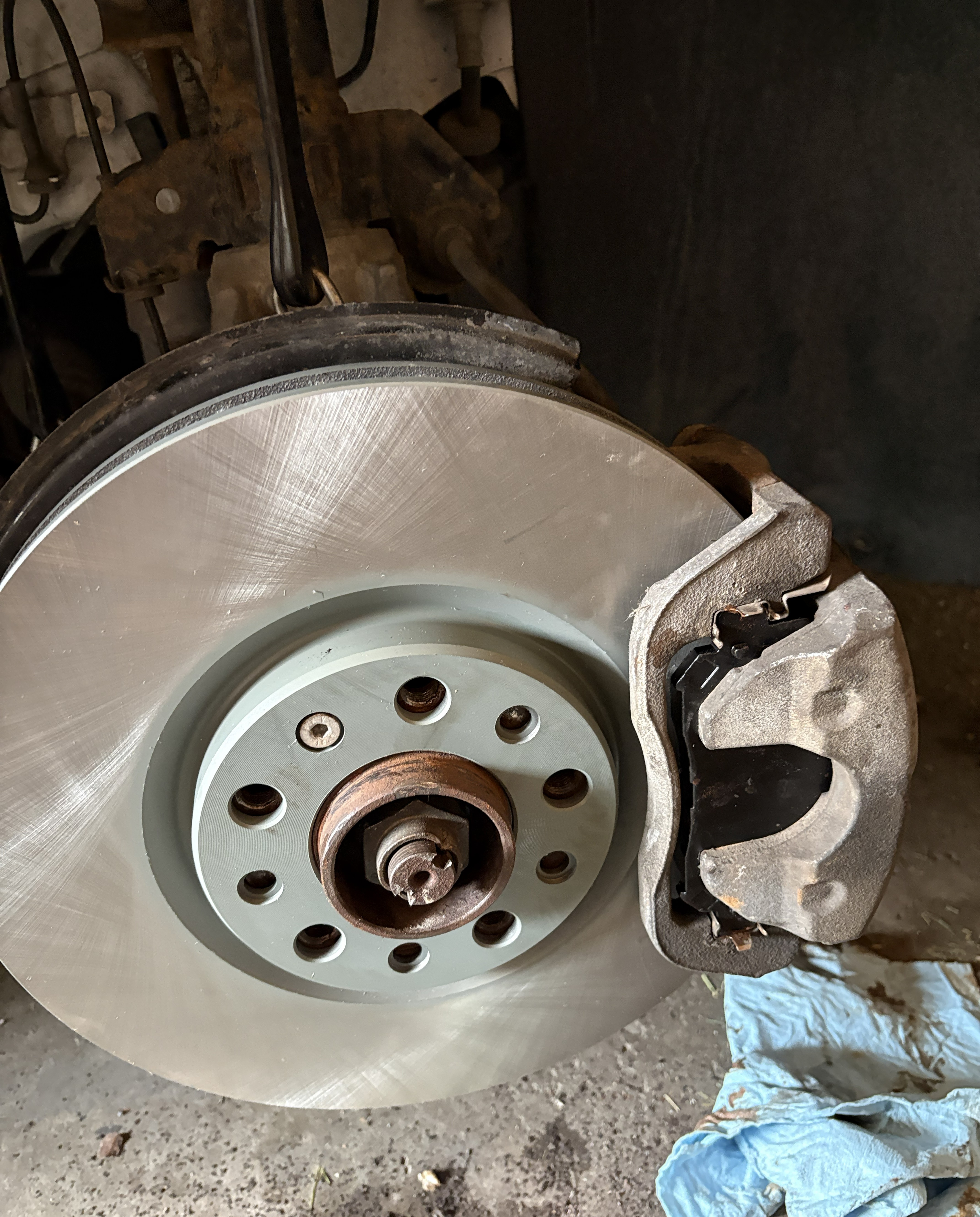
To improve braking performance and stopping power, the worn-out pads and rotors at all four wheels were replaced.
As such, this involved removing the old components, removing rust and debris accumulation from the hardware, and relubricating the necessary components prior to the installation of the new parts.
Pictured is a deeply pitted old rotor, the fresh replacement rotor and pads on clean hardware, and the wide array of hand and pneumatic tools used to complete the repair.
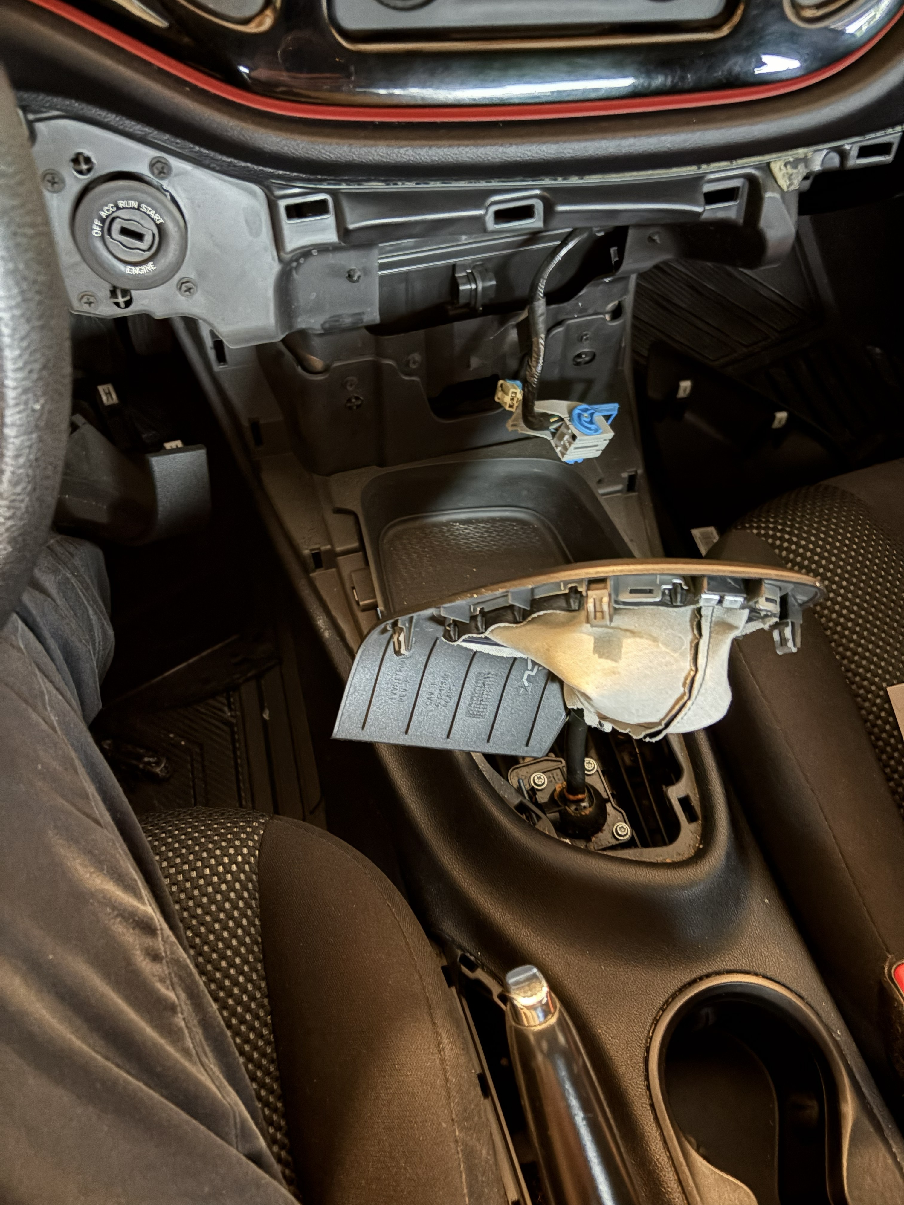
The interior trim removed
The handbrake was found to be non-functional at the time of the vehicle's purchase; it would not engage at all, rendering it useless for parking and emergencies. In an effort to restore its function, the entire interior trim, across the dashboard and into the glovebox had to be removed to access the handbrake assembly. It was found to have loosened with time, so it was tightened. The handbrake mechanisms on the rear brake calipers were also found to have been partially seized; they were broken loose with a hammer and relubricated. These two efforts together restored the function to the handbrake.
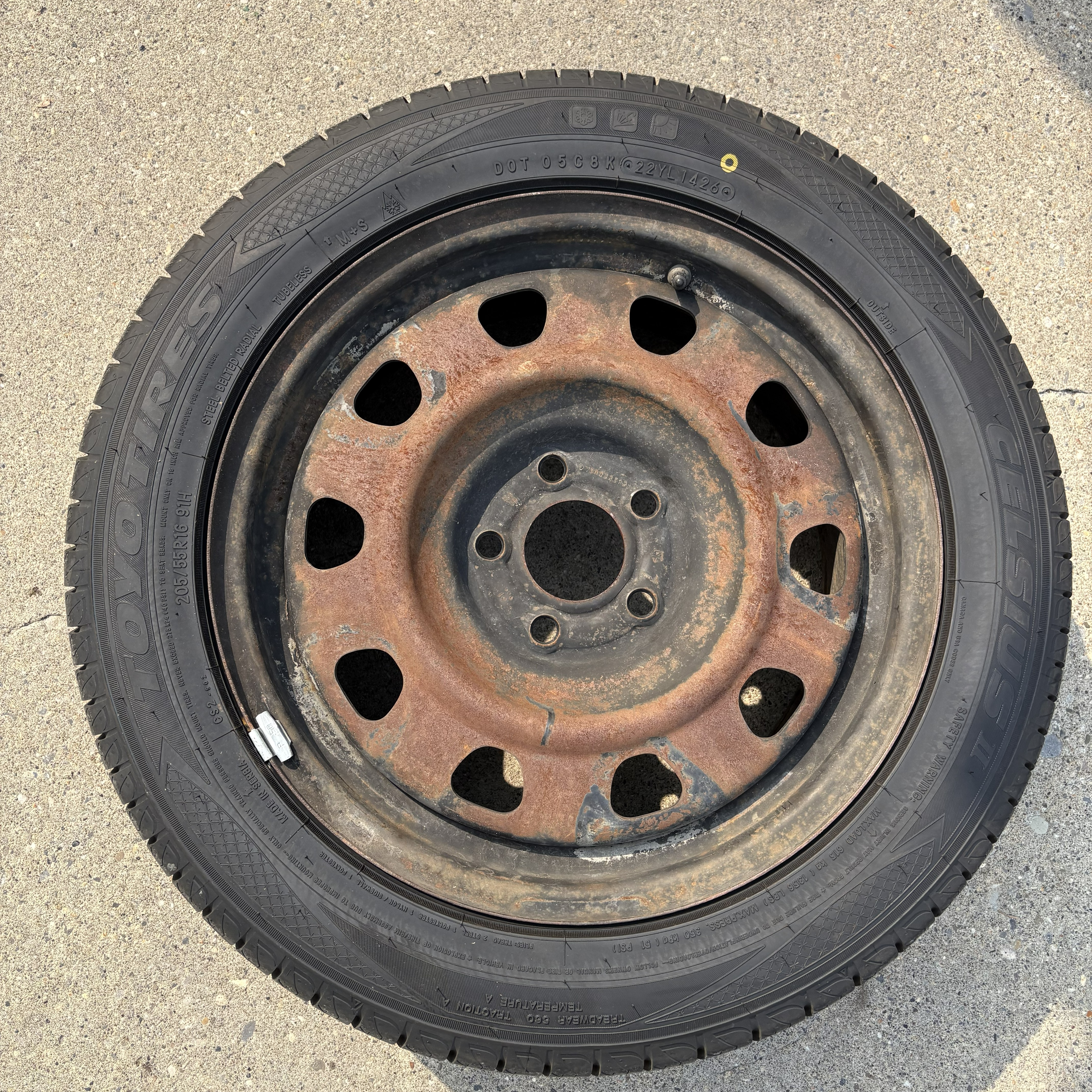
Original Rusted Rim
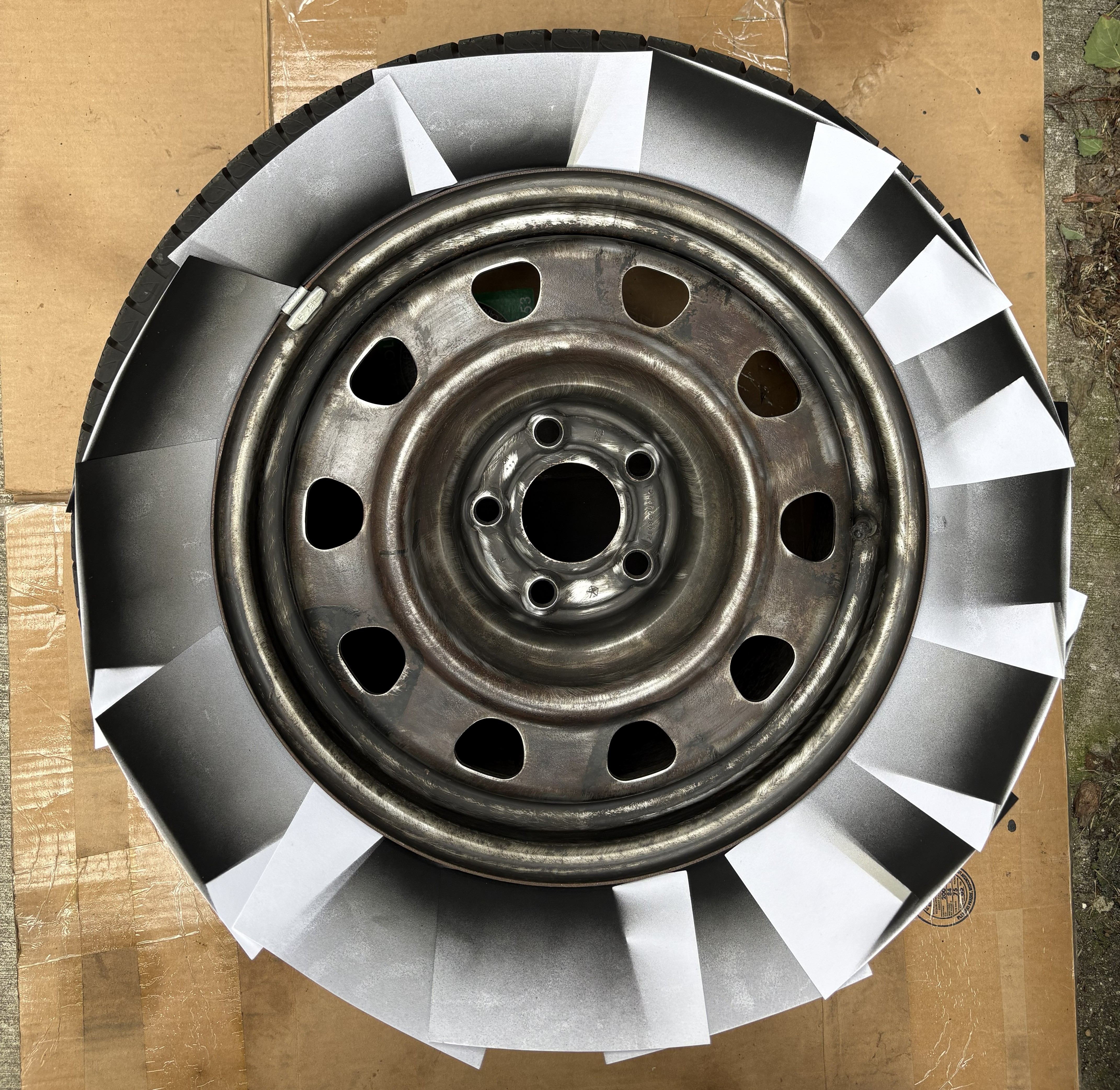
After Wire Brushing
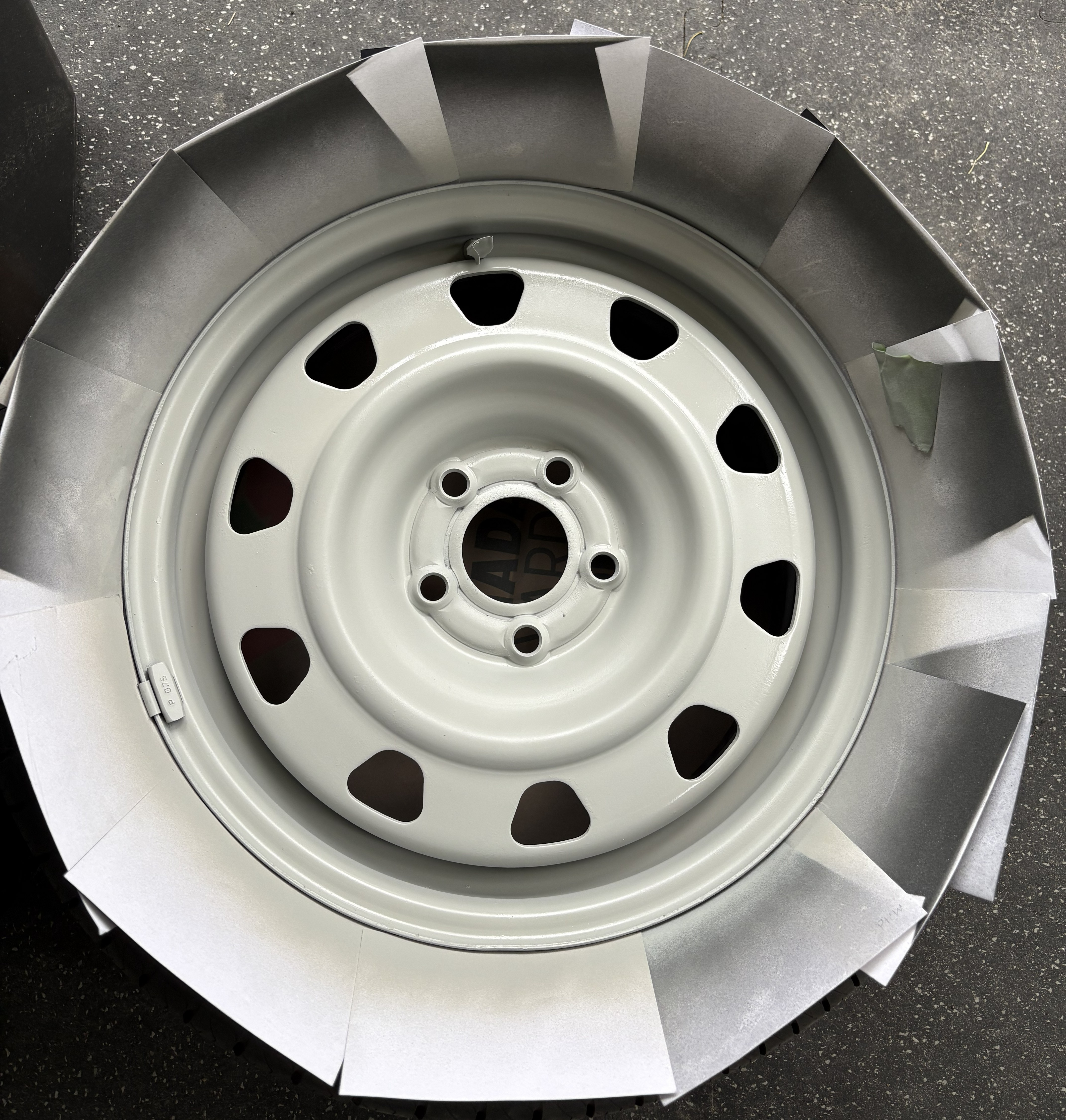
After Priming
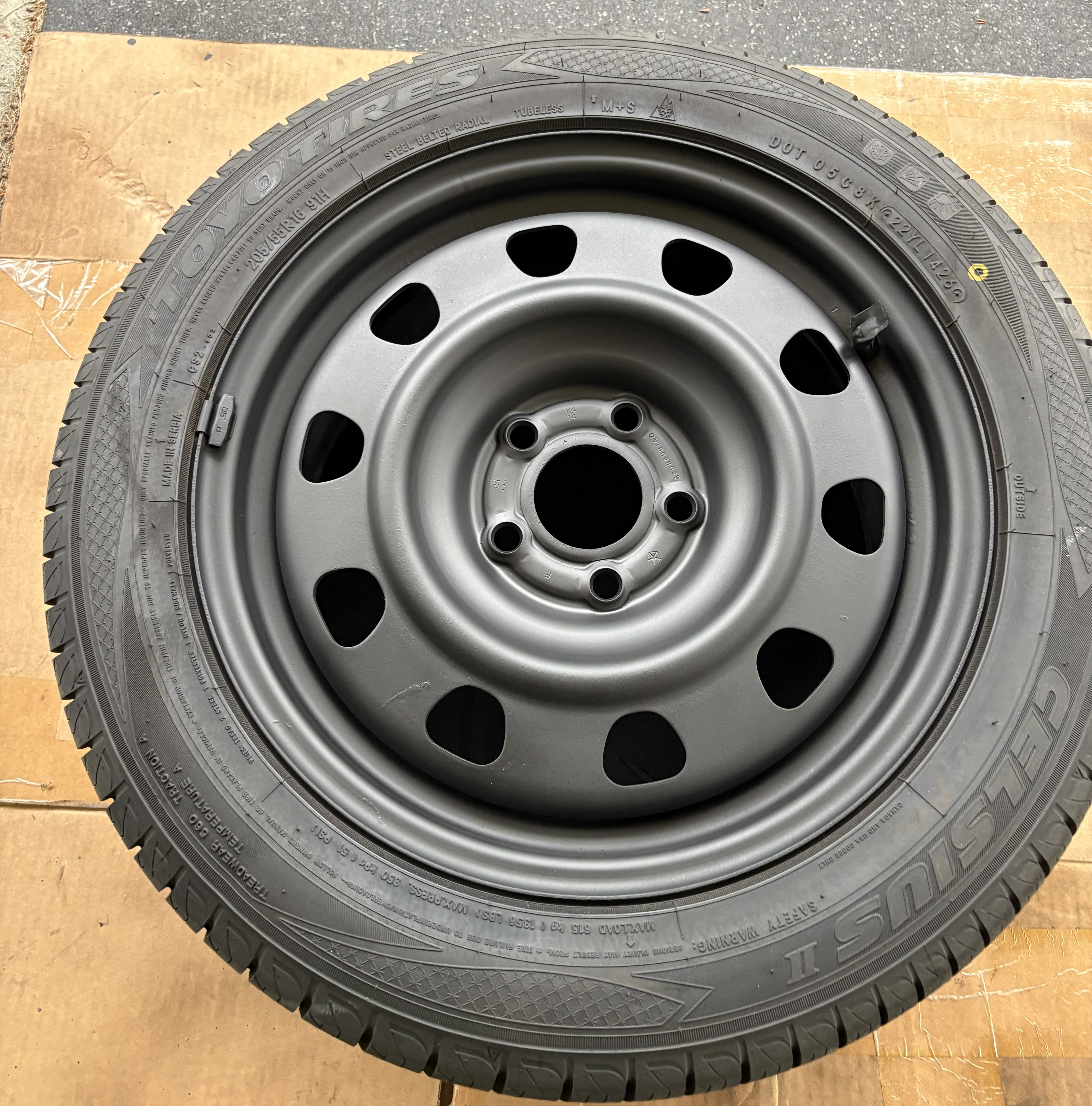
Freshly Painted
Repainting the Rims
For cosmetic reasons, I chose to repaint the rims to matte black, so that they would match the black and white aesthetic of the vehicle.
For this process, the rust and old paint was first removed from the rims using a wire brush attachment on a drill.
Next, the rims were painted with three coats of metal primer, and once dried, painted with four coats of matte-black automotive paint.
The paint was allowed to cure, and the refreshed rims were then reinstalled on the vehicle.
As part of the UBC Engineering first-year curriculum, one project involved designing an adaptive device in the context of a real patient with limited mobility.
Working in a team with four other members, we collectively developed a device to squeeze fluids from tubes to address the patient's limitations with motor and limb function.
Through a process of ideation, prototyping, and selecting potential designs, this device was our final selection. The device was modeled in Fusion 360 and presented through
a technical memorandum detailing the design process and device features. The product was then publicly presented to an audience in an elevator pitch.
Details such as manufacturability potential, reliability, and cost were all factors discussed and considered throughout the process.
I was most involved in producing, screening, and developing designs, and was one of the selected presenters for the elevator pitch.
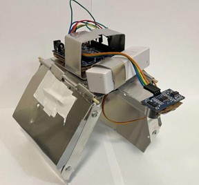
Full view of the claw
As part of the UBC Engineering first-year curriculum, one project was to design, build, and program an autonomous claw for use in a class competition in picking up various objects. Working in a team with four other members, we collectively designed and built a claw from aluminium sheet metal and integrated the electronics for autonomous control.
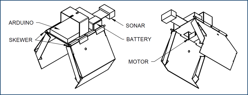
Isometric drawing of the final design
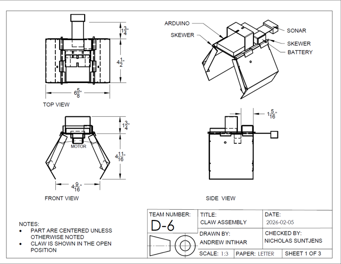
The final design was the result of prototyping and refining several different concepts, with each iteration evaluated on functionality and manufacturability. Problems with initial designs were identified through testing and addressed before the final configuration. The dimensions and critical parameters of the final design were defined in isometric drawings made with Autodesk, which accurately guided the process of fabrication. This ensured fabricated components matched the intended form and function.
Orthographic drawing of the final design
Arduino (C++) was the basis of the autonomous control system, providing the logic to detect and respond to objects in competition.
A sonar depth sensor positioned toward the ground triggered the motor to close the jaws of the claw once in the proximity of an object.
The control system code was repeatedly tested and refined to ensure reliability in competition.
In this project, I was most involved with fabrication of the metal claw, integration of electronics, product testing, and I assisted with programming.
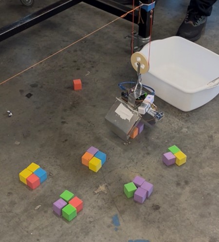
Block competition setup
With the final system in order, the competition consisted of three events: collecting as many assorted items as possible in 2 minutes, collecting as many foam blocks as possible in 2 minutes, and cooperating with other groups to pick up large household items.
Competing against over twelve teams, we successfully collected the most assorted items and foam blocks overall.
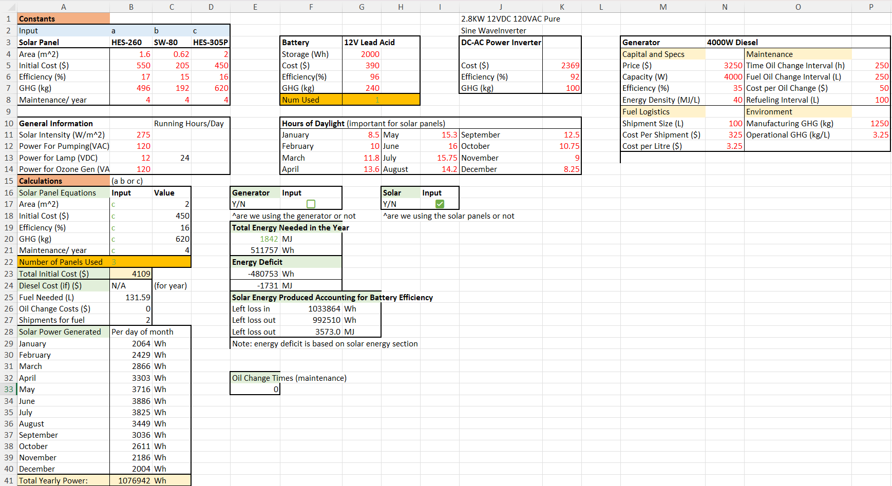
Excel sheet of the power system
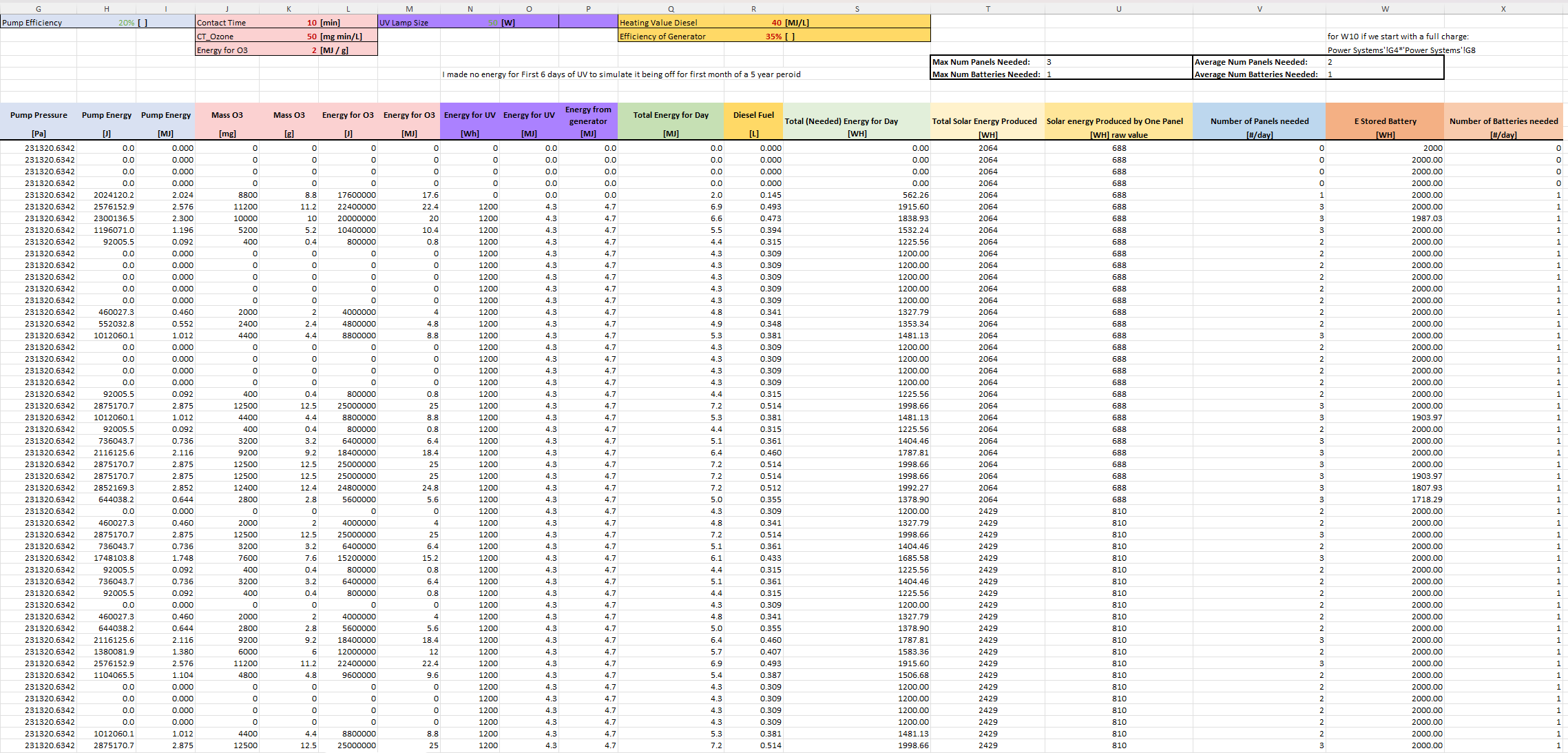
Excel sheet of the energy system
As part of the UBC Engineering first-year curriculum, the final design project was to design a rainwater harvesting system that could be realistically implemented in a remote BC town. With weather data from the town of Van Anda and parameters of water usage and equipment capabilities, the system was modeled through rigorous use of Excel. Weather data and system parameters were incorporated with into calculations for energy usage, greenhouse gas emmissions, fluid dynamics, cost, and other performance metrics. Working in a team with four other members, the simulated system we delivered had an overall satisfaction of 83% year-round, based on a set of user requirements in the simulation.
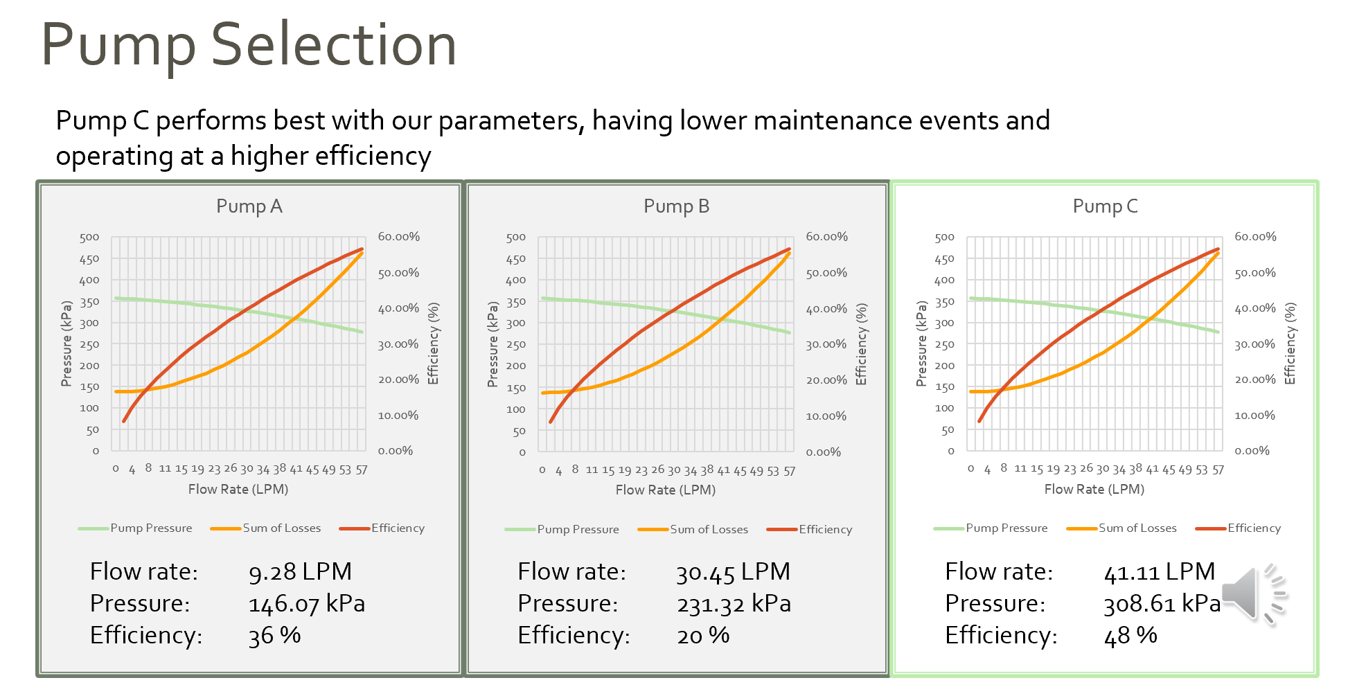
Performance of the pump in the system
Equipment choice, energy sources, and water delivery capabilities were selected in consideration of their benefits and drawbacks to create an optimized system.
For example, in water pump selection, each of the three given choices were plotted in terms of performance, and the best option for our system was selected.
In this part of the project, I primarily oversaw the development of the power systems page and its integration into other sheets.
Final grade - highest score in the cohort
The final system was graded in two phases: through performance with new, variable weather data, and through a graded video presentation.
At a score of 102.2, our video presentation received the highest grade in the year cohort, in a grading process that involved head-to-head comparison of videos and
rubric analysis (our score was boosted above 100% due to scaling).